TRD electronics Status report - PowerPoint PPT Presentation
1 / 16
Title: TRD electronics Status report
1
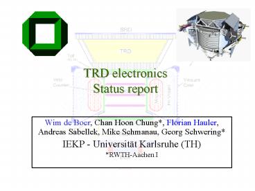
TRD electronicsStatus report
- Wim de Boer, Chan Hoon Chung, Florian Hauler,
Andreas Sabellek, Mike Schmanau, Georg Schwering - IEKP - Universität Karlsruhe (TH)
- RWTH-Aachen I
2
Outline
- QM2 production status of boardsUDR2, UPSFEv2,
UBPv2, S9011AUv2, S9011B - Cosmics test stand
- Working with the system
- UHVG voltage stability
- Preparation for ESS (Environmental Stress
Screening) _at_ CSIST (Temperature cycling,
Vibration and EMI/EMC at CRATE level) has
started - Summary
3
TRD(U)-Electronics Overviewafter weight reduction
Ucrate TRD electronic crate UBP TRD
backplane UPD TRD power distribution box
V2
V2
UPSFE TRD power supply for front end UDR TRD
data reduction board JINF data concentrator and
link to higher DAQ for TRD UHVG TRD high
voltage generator UFE TRD front end UTE TRD
tube end UHVD TRD high voltage distributor
removed USCM USCM functionality covered partly by
JINFV2
4
Full U-crate with QM2 hardware
UHVG
JINF
UDR2
UPSFE
5
Status of TRD electronics
- UDR2 / UPSFEv2 / UBPv2 / S9011AUv2 / S9011B /
DC-DC converters - QM2 production and testing at CSIST finished in
Taiwan last year. - QM2 mechanics of U-Crate and UPD-Box just arrived
- Preparation for ESS (Environmental Stress
Screening) _at_ CSIST Temperature cycling,
Vibration and EMI/EMC has started - Next step is space qualification on crate-level
(e.g. QM2 ESS). - Further system test is foreseen in Aachen
Connection to octagon andoperation with gas
system. Special attention to noise performance
grounding.
6
Cosmics at Karlsruhe
New cosmics test stand at Karlsruhe for long term
data taking.
Trigger A
PM HV
64 channel strawtube jig
Trigger B
Trigger electronics
Power supply
U-Crate
7
Online Display
QT with OpenGL on a Linux operating system
Fe55
Triggered cosmics event colour coding indicates
ADC amplitudes
Averaged Fe55 source hits (random readout) colour
coding indicates mean ADC amplitudes
8
Working with the system 1
- Delay scan
Jinfv2 features tunable delay. Setting 0x70
corresponds to a peaking time of about 2.4 us
9
Working with the system 2
- Voltage Scan Ar/CO2 (80/20)
corrected to 1013 mbar 20C
gas gain 3000
10
Working with the system 3
- Fe55 calibration with random readout
- random readout required since we cannot
trigger on photons (self-triggered
readout would be required) - gas Ar/CO2 (80/20)
- setup tuned for low intensity Fe55 and very
fast readout - gtDSP online data reduction
- Peak determined at 90 of Fermi function
11
Working with the system 4
rough estimation 90 Aachen Monte Carlo
simulation
12
UHVG calibration
UHVG requires calibration. Setup _at_ IEKP with
Keithley 2001 and voltage divider, accuracy lt 2V.
20 C
(setting 3000hex) measurement of 42 channels max
spread is 21V
long term voltage stability requires further
investigation. (VK) seems to depend on
temperature.
13
QM2 UPSFE testsUPSFE Test-Workbench
geom. address
Monitor lines
status LEDs for UHVG,UDR2 ON/OFF
LeCroy
Dallas Temp. sensor bus
variable load (28x)
UPSFEv2 slot
power connections
USB interface
14
QM2 UPSFE tests Variable load
Max 890L MOSFET
Status LED
Opto-coupler
-2.0V
UPSFEv2
feed back to PC (via MC)
2.0V
DS 1803 Digital Potentiometer
Load resistor
control lines from PC (via MC)
15
QM2 UPSFE tests Control software
- Labview Software for UPSFE tests
- automatic testing of 14 UPSFE channels
- ramping load
- reading linear regulator feed back and
storing switch-off currents. - monitoring of UPSFE supply currents
16
ESS preparations
- ESS in preparation
- Target date is August 15th
- Successfull preparation depends on a few
factors- All parts have to be available to
assemble the new UPD-Box (and U-Crate) with
QM2 mechanics. (electrically and mechanically)-
new firmware for S9011AUv2 and UPSFEv2 has to be
ready - To benefit from work already done, we will use
the Tracker software (Daniel Haas). - ESS consists of temperature cycling, vibration
test and EMC/EMI tests.
17
TRD front end simulator (UFS) for TVT at NSPO
During TVT, not enough real front ends will be
available. A device is needed to simulate the
load to the USPFE-boards and to answer the
signals of the UDR2-boards to recognize any
faults.
Load resistors
UPSFE
Heat Interface
Power for front ends
Load resistors
DAC level
DAC
ADC
control signals
UDR2
UFS
Clock ADC
FPGA/DSP
LVDS
digitzed DAC level
18
ESS configuration
UPD-Box
U-Crate
UFS (Front End Simulator)
19
Summary
- All QM2 boards for TRD are tested and are
available for space-qualification. - ESS test preparation has started. Frontend
Simulator (UFS) production finished. Target date
for ESS is August 15th. - QM2 mechanics for UPD-Box and U-crate have just
arrived. Integration this week. - Long term tests with cosmics stand shows no major
problems in operation. - VK investigating UHVG voltage stability.
- OK for flight module production will be given, as
soon as system tests and space qualification
tests have been completed. (TVT, vibration, )


