Status of Phase II Energy Loss Studies - PowerPoint PPT Presentation
1 / 12
Title:
Status of Phase II Energy Loss Studies
Description:
X (cm) Axial Distribution of Halo Interactions in the Second Primary ... 1. Collimator data, ray files, and loss maps from LHC Collimator web page, Feb. 2005. ... – PowerPoint PPT presentation
Number of Views:16
Avg rating:3.0/5.0
Title: Status of Phase II Energy Loss Studies
1
Status of Phase II Energy Loss Studies
L. Keller LHC Collab. Mtg., 15-17 June, 2005
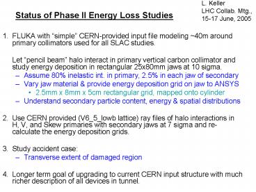
- 1. FLUKA with simple CERN-provided input file
modeling 40m around primary collimators used for
all SLAC studies. - Let pencil beam halo interact in primary
vertical carbon collimator and study energy
deposition in rectangular 25x80mm jaws at 10
sigma. - Assume 80 inelastic int. in primary, 2.5 in
each jaw of secondary - Vary jaw material provide energy deposition
grid on jaw to ANSYS - 2.5mm x 8mm x 5cm rectangular grid, mapped onto
cylinder - Understand secondary particle content, energy
spatial distributions - Use CERN provided (V6_5_lowb lattice) ray files
of halo interactions in H, V, and Skew primaries
with secondary jaws at 7 sigma and re-calculate
the energy deposition grids. - 3. Study accident case
- Transverse extent of damaged region
- 4. Longer term goal of upgrading to current CERN
input structure with much richer description of
all devices in tunnel.
2
IR-7
Beam 2
X (cm)
Beam 1
dipoles
First group of secondary collimators
Primary collimators
40 m
Z (cm)
3
Axial Distribution of Halo Interactions in the
Second Primary Collimator (TCPH)
Carbon
4
Axial Position of Halo Interaction Point vs.
Distance from Primary Collimator Edge
Why a sharp peak 1µ from the edge?
Beam
Jaw edge
5
Energy Spectra of Particles Hitting TCSH1
All Particles-7s
Keller 2004-10-06
6
Spatial Distribution of Particles from TCPV at
face of TCSH1 when Jaws at 7 sigma
Upper right jaw
Lower left jaw
7
Concentrating E_dep in the Front Part of the
Jaws(Use CERN-provided ray files)
Carbon pre-radiator
Tungsten with carbon pre-radiator
8
Power Deposition on First Secondary Collimator in
12 Min. Lifetime
(kW per jaw)
Notes 1. Collimator data, ray files, and loss
maps from LHC Collimator web page, Feb. 2005. 2.
Must add contribution from direct hits on
secondary jaws.
9
Missteered beam (9E11 protons) on secondary
Jaw What is the damage area in a missteering
accident?
Copper Jaw
3D ANSYS model, E. Doyle
Cross section at shower max.
Copper
2.5 cm
Fracture temp. of copper is about 200 deg C
10
Accident Case jaw adjacent to the one being
directly hit, 4 mm gap. This jaw may be
damaged too.
Copper
3D ANSYS model, E. Doyle
Copper
Fracture at 200deg C
840 deg C
11
Another accident Case Beam hits the horizontal
primary collimator The first jaw in the downbeam
secondary collimator (40m away) may be damaged.
Copper
3D ANSYS model, E. Doyle
Copper
250 C
12
- Discussion Items for June 2005
Collaboration Meeting - A. IR7 FLUKA Model
- 1. Steps to run at SLAC? (Major progress 16
June) - 2. Modify for cylindrical secondary collimators?
- 3. Energy loss distribution with all copper
secondaries except TCSM.A6L7 is carbon. - Distribution of Accidental Hits in IR7? Ralph
- How much simulation has been done w/ the 60 cm
primary collimators? - 1. Inefficiency?
- 2. Hit distribution on all secondaries?


