
September 2002 L1.1 - PowerPoint PPT Presentation
1 / 10
Title:
September 2002 L1.1
Description:
... the radial distortion of the lenses, which would give an additional intrinsic ... The line will intersect the camera planes at and , known as the epipoles. ... – PowerPoint PPT presentation
Number of Views:44
Avg rating:3.0/5.0
Title: September 2002 L1.1
1
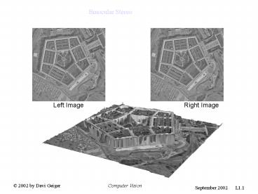
Binocular Stereo
Left Image
Right Image
Binocular Stereo
2
Binocular Stereo
- There are various different methods of extracting
relative depth from images, some of them are
based on - relative size of known objects,
- occlusion cues, such as presence of T-Junctions,
- motion information,
- focusing and defocusing,
- relative brightness.
- Moreover, there are active methods such as the
use of Radar or Laser to extract depth
information from scenes, which requires beams of
sound waves or laser waves to be emitted. - Stereo vision has one advantage over other
methods it is passive and accurate.
3
Human Stereo Random Dot Stereogram
Juleszs Random Dot Stereogram. The left image,
a black and white image, is generated by a random
program that assigns black or white at each pixel
according to a random number.
The right image is constructed from the left
image in the following way an imaginary square
inside the left image is displaced a few pixels
to the left and the empty space is filled with a
random generator. When the stereo pair is shown,
the observers can identify/match the imaginary
square on both images and consequently see a
square in front of the background. It shows that
stereo matching occurs without recognition.
4
Human Stereo Illusory Contours
Not even the identification of illusory contour
is known a priori of the stereo process. These
pairs gives evidence that the human visual system
does not process illusory contours/surfaces
before processing binocular vision. Accordingly,
binocular vision will be described as a process
that does not require any recognition or contour
detection a priori.
5
Human Stereo Half Occlusions
An important aspect of the stereo geometry are
half-occlusions. There are regions of a left
image that will have no match in the right image,
and vice-versa. Unmatched regions, or
half-occlusion, contain important information
about the reconstruction of the scene. Even
though these regions can be small they affect the
overall matching scheme, because the rest of the
matching must reconstruct a scene that accounts
for the half-occlusion.
Leonardo DaVinci had noted that the larger is the
discontinuity between two surfaces the larger is
the half-occlusion. Nakayama and Shimojo in 1991
have first shown stereo pair images where by
adding one dot to one image, like above,
therefore inducing occlusions, affected the
overall matching of the stereo pair.
6
Projective Camera
Let be a point in the 3D world
represented by a world coordinate system. Let
be the center of projection of a camera where
a camera reference frame is placed. The camera
coordinate system has the z component
perpendicular to the camera frame (where the
image is produced) and the distance between the
center and the camera frame is the focal
length, . In this coordinate system the point
is described by the vector
and the projection of this
point to the image (the intersection of the line
with the camera frame) is given by the point
, where
7
Projective Camera Coordinate System
y
where the intrinsic parameters of the camera,
, represent the size
of the pixels (say in millimeters) along x and y
directions, the coordinate in pixels of the image
(also called the principal point) and the focal
length of the camera.
O
x
We have neglected to account for the radial
distortion of the lenses, which would give an
additional intrinsic parameter. Equation above
can be described by the linear transformation
8
Two Projective Cameras Epipolar Lines
P(X,Y,Z)
y
y
x
Or
er
el
Ol
pr(xo,yo,f)
pl(xo,yo,f)
f
f
x
z
z
epipolar lines
The line will intersect the camera
planes at and , known as the epipoles. A
3D point P projected on both cameras. Each 3D
point is associated to a pair of corresponding
epipolar lines, which are the intersections
between the plane and the left and right
camera frames. Therefore, the epipoles belong to
all pairs of epipolar lines, i.e. the epipoles
are the center/intersection of all epipolar
lines.
9
Estimating Epipolar Lines and Epipoles
The two vectors, , span a 2 dimensional
space and that their cross product,
, is perpendicular to this 2 dimensional space.
Therefore
where
F is known as the fundamental matrix and needs to
be estimated
10
Computing F (fundamental matrix)
- Eight point algorithm
- Given two images, we need to identify eight
points or more on both images, i.e., we provide n
? 8 points with their correspondence. The points
have to be non-degenerate. - Then we have n linear and homogeneous equations
- with 9 unknowns, the components of F. We
need to estimate F only up to some scale factors,
so there are only 8 unknowns to be computed from
the n ? 8 linear and homogeneous equations. - If n8 there is a unique solution (with
non-degenerate points), and if n gt 8 the solution
is overdetermined and we can use the SVD
decomposition to find the best fit solution.
Recommended
CrystalGraphics Presentations


