A. Bertarelli - PowerPoint PPT Presentation
Title:
A. Bertarelli
Description:
Mechanical Engineering and Thermo-mechanical Analysis of ... Mean Asperity Slope. Da. P. P. EG. Less than 1% of the interface surfaces is usually in contact ... – PowerPoint PPT presentation
Number of Views:57
Avg rating:3.0/5.0
Title: A. Bertarelli
1
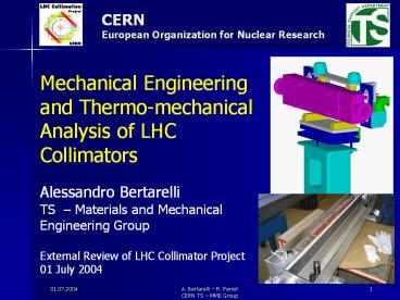
CERN European Organization for Nuclear Research
Mechanical Engineering and Thermo-mechanical
Analysis of LHC Collimators Alessandro
Bertarelli TS Materials and Mechanical
Engineering Group External Review of LHC
Collimator Project 01 July 2004
2
OUTLINE
- Project Requirements
- Design strategy
- Technical design
- Thermal and Mechanical Calculations
- Conclusions
3
PROJECT REQUIREMENTS
- Functional specification (Mechanical aspects)
- High absorbed heat load (up to 32 kW)
- Very high precision (25mm on 1200mm)
- High robustness in accident cases (up to 700ºC)
- Low-Z, high conductivity materials for jaw
(carbon based) - Limited jaw temperature (lt50º C) for outgassing
reasons - Easy maintenance
- Schedule (see M. Mayers talk for details)
- Design Activity started in September 2003
- First full prototype TCS by May 2004
4
DESIGN STRATEGY
- How to meet the challenging requirements ?
- Highest priority to Secondary Collimators (TCS)
- Contribution of many experts
- Wide exploitation of LEP experience
- In-depth calculations carried out from the early
stages of development (concurrent design) - Mix of traditional and edge technologies.
- Advanced Materials (C/C composites, GlidCop ).
- Specific tests to validate most critical
technologies (S. Calatronis talk)
5
TECHNICAL DESIGN
- Main Features (TCS design)
- Multi-DoF internal alignment system.
- Monolithic jaw (1200mm) clamped to the support.
- Decoupling and compensation of thermal
deformations. - Cooling system.
- RF contacts for low impedance.
- Actuation system (2 step-motors per jaw).
- External alignment system and plug-in
- Electronic controls
6
TECHNICAL DESIGN Mechanical Assembly
Overall length 1480mm Tank width 260mm
Vacuum Tank
Actuation system
Beam axis
Main support and plug-in
External adjustment motor
7
TECHNICAL DESIGN Collimator Cross-section (1/2)
Jaw stroke 30/-5 mm
Jaw (25x80x1200 mm)
Support Bar
Cooling Pipes
Clamping springs
Bellow
Stepper Motor
Return Spring
8
TECHNICAL DESIGN Collimator Bloc
1. Jaws in C/C or graphite 2. Cooling Cu-pipes
and plate pressed against the jaw, brazed to the
bar. 3. GlidCop support bar and clamping plates
- Low thermal contact resistance (P35 bar)
- Differential thermal expansion allowed
- Deformations minimized (compensation)
1
2
3
9
TECHNICAL DESIGN Actuating System
1. Jaw actuated by 2 stepper-motors via a roller
screw (10 mm/step) 2. Return spring for semi -
automatic pullback and play recovery 3.
Rack-pinion system to prevent misalignments 4.
Vertical sliding of the jaw surface (? 10mm)
3
2
1
2
3
1
10
TECHNICAL DESIGN Cooling System
- Jaw cooled by 2 Ø6 OFE-Cu pipes (3 loops each)
- Outer section squared (?9) to allow brazing to
internal and external plates - Water from general cooling circuit (Inlet temp.
up to 27ºC) - Water flow 5 l/min (20 l/min per collimator)
leading to a 3 m/s velocity
11
THERMOMECHANICAL ANALYSIS
- Main problems to tackle in analysis and design
- How to evacuate heat loads?
- How to join graphite jaw and metal support?
- How to keep thermal deformations to a minimum?
12
THERMOMECHANICAL ANALYSIS
- Extensive analytical and numerical calculations.
- Semi-analytical models for Thermal contact
resistance, Convection, Thermal bending - Many FE models (ANSYS) of the TCS were studied
- 2- and 3-dimensional
- Different materials (C/C, C, Cu, Steel,
Glidcop) - Input thermal load imported from FLUKA
simulations - Different load cases (nominal, accident,
transient) - Complex boundary conditions
13
THERMOMECHANICAL CALCULATIONS
How to evacuate heat and allow free expansion
P
RMS Roughness Rq
kG
EG
kCu
Mean Asperity Slope Da
P
- Less than 1 of the interface surfaces is usually
in contact - Pressure is necessary to increase the effective
contact surface - Thermal conductance might be evaluated
analytically
14
THERMOMECHANICAL CALCULATIONS
How to minimize thermal deformations
M1
M2
DT
M3
uiaDT/B duL2/8
the principle of compensation is used
15
THERMOMECHANICAL CALCULATIONS
FEM Model for 3-D analysis
Convection (12360W/m2/K) inlet temp. (27ºC)
Temperature - dependent properties (when
available)
Geom. B.C. Hinged Free expansion
Deposited Heat Power (W/m3)
Contact elem. (friction therm. Conductance)
Preloaded Springs (5 bar)
16
THERMOMECHANICAL CALCULATIONS
- Remarks on jaw materials
- Several materials were analyzed for the jaws
- Snecma NB31 3-d C/C (Y max X min)
- Snecma NB31 3-d C/C (Z max Y min)
- SGL C1001 2-d C/C
- Tatsuno AC150 2-d C/C
- SGL R4550 isotropic graphite
- Out of these only AC150 and R4550 were retained
since they present the best compromise in terms
of deformations, strength and availability.
17
THERMOMECHANICAL CALCULATIONS
Thermal analysis Nominal Conditions 7 TeV 8e10
p/s Steady-state (p5 bar)
2-D C/C AC150 TMax 47ºC
Graphite R4550 TMax 51ºC
18
THERMOMECHANICAL CALCULATIONS
Displacement analysis Nominal Conditions 7 TeV
8e10 p/s Steady-state
2-D C/C AC150 dMax20mm
Graphite R4550 dMax14mm
19
THERMOMECHANICAL CALCULATIONS
Displacement analysis Nominal Conditions 7 TeV
4e11 p/s Transient (after 10s) To be confirmed
2-D C/C AC150 dMax30mm
Graphite R4550 dMax47mm
20
THERMOMECHANICAL CALCULATIONS
Stress Analysis Nominal Conditions 7 TeV 8e10 p/s
steady-state
2-D C/C AC150 sMax7.8MPa
Graphite R4550 sMax5.8MPa
21
THERMOMECHANICAL CALCULATIONS
Stress Analysis Accident case 7 TeV 9.1e11 p (200
ns)
AC150 Tmax 724º R4550 Tmax 698º
Courtesy A. Dallocchio
22
THERMOMECHANICAL CALCULATIONS
Load case summary
Notes Rsadm(1-n)/Ea
23
CONCLUSIONS
- Based on the given requirements, technical layout
is a mix between traditional and new solutions - Mechanical design was finalized
- Feasibility confirmed by prototype manufacturing
- Extensive thermo-mechanical analyses results
predict that tough specification should be
attained within reasonable limits, - provided available data are correct (material
characterization results are forthcoming) - and new Fluka simulations confirm previous
loads. - In nominal conditions stresses are well below the
limits. - Special attention must be given to accident
scenarios, where stresses come close to
admissible limits (see O. Aberle talk)


