System Structure - PowerPoint PPT Presentation
1 / 25
Title:
System Structure
Description:
Fairing geometry defined by 11 parameters. bow. stern face. maximum thickness ... Positioning the fairing. reference points. UTP Spring Conference, March 26/27. ... – PowerPoint PPT presentation
Number of Views:34
Avg rating:3.0/5.0
Title: System Structure
1
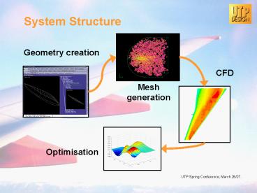
System Structure
Geometry creation
CFD
Mesh generation
Optimisation
2
Flap-track fairings
3
Geometry constraints
4
ICAD
- LISP programming code interface
- Geometry creation initially seems complex and
longwinded
5
ICAD
6
ICAD
- Easy parameterisation of geometry
7
- Fairing geometry defined by 11 parameters
Front view
vertical sides
stern face
bow face
curved hull
Side view
Intersection with wing
stern
bow
maximum thickness section
8
- Fairing geometry build-up
9
- Positioning the fairing
reference points
10
- Fairing attached to wing
11
- Boundary defined around wing
12
System Structure
Geometry creation
CFD
Grid generation
Optimisation
13
GAMBIT
- Non-parallel
- Coarse unstructured mesh 250,000 1,000,000
cells - Batch-run via journal files
- Import IGES file
- Clean up the geometry
- Build volume
- Mesh
- Edges
- Faces
- Volume
- Specify Boundaries
- Export to FLUENT
14
System Structure
Geometry creation
CFD
Grid generation
Optimisation
15
FLUENT
- Parallel solver
- Batch-runs via journal files
- Spawn nodes
- Read partition mesh
- Set up solution
- Iterate and write data
16
Initial manual runs
Mach no. on lower surface
Mach no. on upper surface
17
System Structure
Geometry creation
CFD
Grid generation
Optimisation
18
We now have a way of
- Creating a parameterised geometry
- Creating a mesh around the geometry
- Solving the flow around the geometry
We need to automate this process
19
System Structure
Local host
Remote host/s
IDL file GAMBIT journal file FLUENT log file
Parameter data entry (DOE)
Submit node
Job scheduler
GAMBIT FLUENT
ICAD
. . .
Design point 2
Design point 1
Response surface model
20
Iridis
- One of the largest computational facilities in
the UK - Beowulf cluster
- 324 processors consisting of 292 1000Mhz Intel
Pentium III's, and 32 1500Mhz Intel Pentium IV's - 112Gb of memory
- 7.1Tb of local disk storage
- 2.8Tb on RAID5 disk array
21
Design of Experiments gt Response Surface Model
- Expect to see trends between varying parameters
and calculated drag - Latin Hypercube
22
Sample Run
- 40 design points
- Yaw angle from -15 - 15
- Overhang form 10 - 50
- 1,000,000 mesh volumes
- Spalart-Allmaras till drag convergence 500it
- 16 nodes requested for 5hrs per design point
- Run time 2wks
23
DoE gt Response Surface Model
- Kriging
- Low number of design points
- CFD computationally expensive
24
Initial findings
CD
L/D
CL
40 overhang -4.5 yaw
25
(No Transcript)


