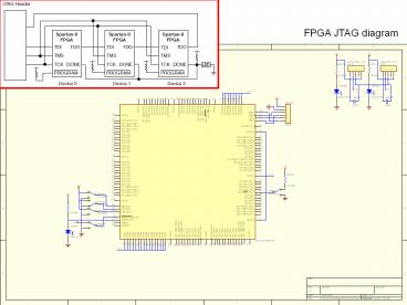
FPGA JTAG diagram - PowerPoint PPT Presentation
1 / 2
Title: FPGA JTAG diagram
1
FPGA JTAG diagram
2
Solution 1 This error, which signifies that the
first bit read out on TDO is invalid, is nearly
always due to a signal integrity problem. The
error essentially indicates that either the power
source is not compliant with power requirements
(it supplies an incorrect voltage or is incapable
of providing the necessary current at the
required voltage level), the board connections
are incorrect, or a disconnect has occurred in
one, or more, of the nets connecting to the
device JTAG pins. To debug this error, first
ensure all devices in the chain are defined.
(i.e., IR length is specified correctly for
non-Xilinx devices). Then disconnect your
programming cable from the board and device under
test and probe the cable pins using an
oscilloscope or logic analyzer to ensure that the
cable is indeed behaving as expected. Expected
behavior for the IDCODE looping sequence is
outlined in the software manuals --gt iMPACT User
Guide --gt Troubleshooting for Boundary-Scan
Chains --gt Boundary-Scan Chain Debug. A good way
to ensure that your cable is working correctly is
to also use the "Debug Chain..." functionality
under "File" in the Impact menu bar. This feature
will allow you to apply known voltage levels to
TDI and TMS to ascertain proper functionality.
Now, with the cable still disconnected and
power applied to the device under test, probe TDI
and TMS both should be at a logic "high" since
they're pulled up internally. Note that Vref must
be connected to a reference voltage for this to
hold true. If TDI and TMS are not at "high" as
expected, you likely have power problems. Now,
reset the cable by using Output --gt Cable Reset
in Impact and connect it to the board and device
under test again. Use the "Debug Chain" feature
once more to drive TDI and TMS both low and high
and probe the device under test pins to verify
that they take on the expected voltage values. If
not, then you have a disconnect between the cable
and device, or possibly the net that connects the
two is inadvertently shorted to ground or Vcc. If
you suspect, to provide an example, that the net
is shorted to ground, you can test that notion by
powering down the system and measuring the
resistance from the net in question to system
ground. If all is wel l, such a test should yield
a high resistance value (likely MOhms).
Finally, if all tests are inconclusive up to
this point, then perform the idcode looping
operation again with everything connected. Probe
TCK to ensure you have a valid, clean clock
signal, probe TMS to verify that it's toggling,
and probe TDO to see that it also toggles. The
Impact Guide in the software manuals, as
referenced above, provides details about what the
toggling waveforms should look like. If
everything is functioning as expected, but TDO
isn't toggling, then the device under test may be
faulty. If TDO is, indeed, toggling, but you
still get the software error this solution
addresses, then if you need assistance, please
open a WebCase at http//support.xilinx.com/supp
ort/clearexpress/websupport.htm
ERROR message ERRORiMPACT635 - Boundary-scan
chain test failed at bit position '1'. A
problem may exist in the hardware
configuration. Check that the cable, scan
chain, and power connections are intact, that
the specified scan chain configuration matches
the actual hardware, and that the power
supply is adequate and delivering the correct
voltage.PROGRESS_END - End Operation.
Adopted from XAPP501_Configuration quick start
guidelines.pdf Xapp188_Configuration and readback
of Spartan-II FPGAs using
boundary scan.pdf


