Emittance Probe 1 (side) - PowerPoint PPT Presentation
Title:
Emittance Probe 1 (side)
Description:
Emittance Probe 1 (side) Distance from slit to detector: 4.470 inches Detector with multiple collectors Expected collector width based on individual measurements: 0 ... – PowerPoint PPT presentation
Number of Views:40
Avg rating:3.0/5.0
Title: Emittance Probe 1 (side)
1
Emittance Probe 1 (side)
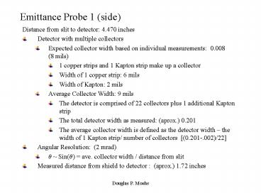
- Distance from slit to detector 4.470 inches
- Detector with multiple collectors
- Expected collector width based on individual
measurements 0.008 (8 mils) - 1 copper strips and 1 Kapton strip make up a
collector - Width of 1 copper strip 6 mils
- Width of Kapton 2 mils
- Average Collector Width 9 mils
- The detector is comprised of 22 collectors plus 1
additional Kapton strip - The total detector width as measured (aprox.)
0.201 - The average collector width is defined as the
detector width the width of 1 Kapton strip/
number of collectors (0.201-.002)/22 - Angular Resolution (2 mrad)
- ? Sin(?) ave. collector width / distance from
slit - Measured distance from shield to detector
(aprox.) 1.72 inches
2
Emittance Probe 2 (top)
- Distance from slit to detector 4.525 inches
- Detector with multiple collectors
- Expected collector width based on individual
measurements 0.008 (8 mils) - 1 copper strips and 1 Kapton strip make up a
collector - Width of 1 copper strip 6 mils
- Width of Kapton 2 mils
- Average Collector Width 8.8 mil
- The detector is comprised of 22 collectors plus 1
additional Kapton strip - The total detector width as measured (aprox.)
0.196 - The average collector width is defined as the
detector width the width of 1 Kapton strip/
number of collectors (0.196-.002)/22 - Angular Resolution (1.95 mrad)
- ? Sin(?) ave. collector width / distance from
slit - Measured distance from shield to detector 1.72
inches (from probe 1)
3
(No Transcript)
4
Probe 1 and Probe 2 Output Channel mapping
Conversion To current Channels 20 0 1 2 3
4 5 6 7 8 9 10 11 12 13 14 15 16 17
18 19 20
Outer most
Probe pin numbers 21 1 2 3 4 5 6 7 8
9 10 11 12 13 14 15 16 17 18 19 20 21
Shield Pin 22 Pin 23,24 are not used Pin 25
grouned
Inner most
5
Basic Operation
- Probes 1-4 all use the same amplifiers. Thus
each time a probe is used the correct cable in
the back of rack LE1-RR2-10 needs to be connected
to the sample and hold unit. - The ACNET channels are
- HVEM00 through HVEM20
- The motor control channels are
- PROBE1 through PROBE4
- Probes 1 and 2 cannot both be in the beam at the
same time because they occupy the same space.
Thus they are interlocked such that one must be
in the out position before the other can be
inserted. Similarly for probes 3 and 4. - To run Probes 3 and 4 the safety system beam
stops need to be out. This means the Linac needs
to be secured. However you do not need to
accelerate beam because these probes are at the
front of Tank 1. - A 700 volt bias on the shields seems to yield
the cleanest signal however this means that
secondary electrons dominate the signal. Beware!
The production of secondary electrons on surfaces
is very dependant on the incident angle of the
primary ion. See the next slide for a rough
correction.
6
Probe2 Secondary Electron Correction
For additional information on secondary electron
emission see Huashun Zhang, Ion Sources, p.
12-13, 1999.
The secondary electron yield (SEY) is the number
of liberated electrons per incident particle, in
this case negative hydrogen. SEY change
nonlinearly with the incident particle energy and
is dependant on the incident angle scaling
roughly as the sec? of the the incident
angle. The probable signal adjustment for Probe
2 is shown here. To correct the probe signal
multiply by the values given here.
7
Probe 1 Secondary Electron Correction


