
P1254325716GkIwV - PowerPoint PPT Presentation
1 / 37
Title:
P1254325716GkIwV
Description:
Afferent (Input) Minder Chen, 1999-2002. Structured design - 23 ... Afferent. Central. Transform. Efferent. Transform Analysis. Minder Chen, 1999-2002 ... – PowerPoint PPT presentation
Number of Views:27
Avg rating:3.0/5.0
Title: P1254325716GkIwV
1
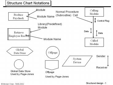
Structure Chart Notations
Calling Module
Module
Normal Procedure (Subroutine) Call
Produce Paycheck
Module Name
Control Flag
Library(Predefined) Module
Retrieve Employee Record
Data
Data
Module Name
Called Module
Offpage
Global Data Store
Sender
System Device
Receiver
Global Data Store Used by Page-Jones
Offpage Used by Page-Jones
2
Module Module1 ' The argument x is passed by
value ' The argument y is passed by
reference Public Sub ABC(ByVal x As Integer,
ByRef y As Integer) ' If ABC changes x,
the changes do not affect a. ' If ABC
changes y, the changes affect b. x x
1 y y 1 End Sub Public Sub
Main() Dim a As Integer 3 Dim b
As Integer 4 ABC(a, b) ' Call the
procedure. Console.WriteLine("a " a)
Console.WriteLine("b " b) '
You can force parameters to be passed by value,
regardless of how ' they are declared,
by enclosing the parameters in extra parentheses.
ABC((x)) End Sub End Module
3
Before After
Dim a As Integer 3 Dim b As Integer 4 ABC(a,
b) Console.WriteLine("a " a) Console.WriteLine
("b " b)
a
3
3
b
4
5
Before After
x
3
4
x
y
y
Public Sub ABC(ByVal x As Integer, ByRef y As
Integer) x x 1 y y 1 End
Sub
4
Structured Chart Notations
Sequence
Decision
Call A,1
A
Call A,1
A
IF Tx-Code A Then Call A,2
Call A,2
ELSE IF Tx-Code B Then Call A,3
Call A,3
ELSE IF Tx-Code C THEN Call A,4
A,1
A,2
A,3
A,4
A,3
A,2
A,1
Iteration
Lexical Inclusion
Call A,1
Call A,1 Statement X Statement Y StatementZ
Call A,3
A
A
Repeat
Call A,2
Call A,3
Call A,4
Until EOF true
A,3
A,1
A,2
Statement X Statement T Statement Z
A,1
A,2
A,3
A,4
5
Structured Chart Notations (Contd.)
Notations used by Page-Jones
Lexical Inclusion (The Hat Symbol)
Decision
Iteration
6
Structure Chart Notations
Concurrent Activation Symbol
Interface Table
Asynchronous Activation of a Subtask
Interface Table
I/F Input Output
1
2
1 A,B C
2 X Y,Z
Physical Packaging Boundary
Information Cluster
Program X
A B C
D
Modules A, B, and C has exclusive access to Data D
7
Sample Structure Chart
2.0 Enter Customer
payments
Remittance
Remittance
Customer-sold-to-name
Customer-sold-to-name
EOT
Customer-ID
Customer-payment
Remittance
2.4 write Customer
payment transaction
2.5 Display Customer
payment
2.2 Add Customer
information
2.3 Update A/R
master
2.1
Key remittance
Monthly-Statement-remittance
Customer-ID
Customer-record
A/R-record
New-A/R-record
Invoice-remittance
Customer-ID
Old-A/R-record
Customer-record
Valid-account
Customer-number
Valid account
Customer-ID
Posting-ok
No-record-on-file
No-record-on-file
2.12 Key monthly statement
remittance
2.32 Verify
Customer account
2.21 Get
Customer record
2.11 Key
invoice remittance
2.33 Rewrite A/R
record
2.22 Verify
Customer account
2.31 Get
receivable record
Structure chart for program 2.0. Enter customer
payment Exercise - 3
8
How would you partition this system?
9
Type of Coupling
Tightness of Coupling
Goodness of Design
Loose
Good
Normal Coupling
Data Coupling
Stamp Coupling
Control Coupling
Common Coupling
Bad
Tight
Content Coupling
10
Normal Coupling
A . Call B using X,Y
.
A . Call B .
Y
X
B
B
Module A and module B are normally coupled if
- A calls B
- B returns to A
All information passed between them are through
parameter passing
11
UPDATE CUSTOMER MASTER FILE
Valid Trans-action
Updated Master Record
Master Record
Master Record
Updated Master Record
Valid Trans-action
GET VALID INPUT
PUT CUSTOMER MASTER
UPDATE MASTER
Transaction is valid
Transaction
Transaction
Master Record
VALIDATE CUSTOMER TRANSACTION
GET INPUT
Transaction
Master Record
Acct Number
GET CUSTOMER MASTER
GET CUSTOMER TRANS
12
Data Coupling
Calculate
Monthly
payment of a House
Mortgage Payment
Loan Amount
Term
Interest Rate
Calculate
Mortgage Payment
Module A and module B are data coupled if
- A
calls B
- B returns to A
- All information
passed between them are through parameter passing
- Each parameter is a data element
13
Stamp Coupling
Calculate
Monthly
Payment
of a House
Mortgage Payment
Customer Loan Record
Calculate
Mortgage
Payment
Two module A and B are data coupled if
-
A calls B
- B returns to A
- All
information passed between them are through
parameter passing - A composite piece of
data is passed from one module to another
14
Control Coupling
Produce
paycheck
Produce
paycheck
Tell the operator that The Employee Record Is
Not Found
Employee Record Not Found
Employee ID
Employee ID
Employee Record
Employee Record
Retrieve Employee Record
Retrieve Employee Record
Control Flag
Descriptive Flag
15
Scale of Cohesion
Types of Cohesion
Visibility
Strength of Cohesion
Maintainability
Functional Black box
Strong
Good
Sequential Not-quite so
Communicational black box
Procedural Gray
Temporal box
Logical Transparent
Coincidental or white box
Weak
Bad
16
Structure Chart and DFD
This module is sequentially cohesive.
This module is communicationally cohesive.
17
Simplify Communicational Cohesion
Employee Name
Employee Name
Employee ID
Employee YTD Total Deduction
Employee ID
Employee ID
Employee YTD Total Deduction
Get Employee Name Calculate YTD Total Deduction
Get Employee Name
Calculate YTD Total Deduction
18
Determine Module Cohesion
Type of Cohesion
Functional
Does activities performed by the module related
to a single problem-related task
YES
Sequential
Is sequence important ?
NO
Communicational
Data
What relates the elements
within the module ?
Flow of control
Procedural
YES
Is sequence important ?
Temporal
NO
Neither data nor control
Logical
YES
Are the activities performed by the elements in
the same category?
Coincidental
NO
19
Customer Account Number
Customer Loan Status
Customer Name
DETERMINE CUSTOMER DETAILS
Customer Name
A Communicationally Cohesive Module Halfway
Up a
Structure Chart
Customer Account Number
Customer Loan Status
Customer Name
DETERMINE CUSTOMER DETAILS
Customer Account Number
Customer Account Number
A Communicationally Cohesive Module at the
Bottom of a Structure Chart
Customer Name
EVALUATE LOAN STATUS
FIND CUSTOMER NAME
Each of These Functionally Cohesive Module is at
the Bottom of a Structure
20
Satellite Trajectory
A Functionally Cohesive Module Very High
in a Structure Chart
GET SATELLITE TRAJECTORY
Ranges
Azimuths
Times
Elevation
GET RANGES
GET TIMES
GET AZIMUTHS
GET ELEVATION
21
The Impact of Module Numbers on Cost
High
Total Cost
Cost
Intermodule Effects (Coupling)
Cost Due to
Intramodule Effects (Cohesion)
Cost Due to
Low
Small
Large
Number of Modules
22
Four Basic Types of Modules
Coordinate control
Transform (Process)
Efferent (Output)
Afferent (Input)
23
Idea System Shape of a Structure Chart
Afferent branch
Transform branch
Efferent branch
24
Bouldings Explanation of GST
- "(General Systems Theory) does not seek, of
- course, to establish a single, self contained
- 'general theory' of practically everything which
- will replace the theories of particular
disciplines. - Such a theory would be almost without content,
- for we always pay for generality by sacrificing
- content, and we can say about practically
- everything is almost nothing. Somewhere however
- between the specific that has no meaning and the
- general that has no content there must be, for
- each purpose and at each level of abstraction, an
- optimum degree of generality. It is the
contention - of the General Systems Theorists that this
- optimum degree of generality is not always
- reached by the particular sciences."
Source http//cimru.nuigalway.ie/david/pdf/SE/Sli
des/Theory.PDF
25
Idea System Shape of a Structure Chart
High fan-out
High fan-in
26
The Procedure of Deriving Structure Charts from
Data Flow Diagrams
Evaluate a detailed DFD
Type of DFD
Identify central transform of the DFD
Identify transaction types and transaction center
of the DFD
Map to transform structure
Map to transaction structure
Refined the Structure Chart
Transaction Analysis
Transform Analysis
27
Transform Analysis
Central Transform
P
P
BOUNDARY
A
A
BOUNDARY
L
OUTPUT
INPUT
B
FUNCTION
FUNCTION
A
A
Afferent
K
P
C
Efferent
E
INPUT
P
FUNCTION
D
DATA STORE B
OUTPUT
B
FUNCTION
B
P
P
J
B
F
INPUT
TRANSFORM
FUNCTION
FUNCTION
D
DATA STORE E
C
A
H
M
D
DATA STORE D
P
P
P
D
OUTPUT
I
G
INPUT
TRANSFORM
FUNCTION
FUNCTION
FUNCTION B
C
D
28
BOSS
E
J
G
F
E, F, G
J I
I
INPUT
INPUT
INPUT
OUTPUT
CENTRAL
OUTPUT
FUNCTION
FUNCTION
FUNCTION
FUNCTION
TRANSFORM
FUNCTION
D
B
C
C
CONTROLLER
B
C
K
E F
J
I
G H
TRANSFORM
TRANSFORM
INPUT
OUTPUT
FUNCTION
FUNCTION
FUNCTION
FUNCTION
A
B
A
A
29
Transaction Analysis
Structure Chart
DFD
Get Customer Transaction
Process Customer Transaction
Get Customer Transaction
Get Customer Transaction
Get Customer Transaction
Tx-Code
Get Customer Transaction
Delete Customer Record
Get Customer Transaction
Change Customer Record
Add New Customer
A Transaction Selection Screen
Customer Information System Main Menu
1. Add New Customer 2. Change Customer
Record 3. Delete Customer Record
30
Determine Implementation Boundaries
Real-time
Manual
On-line
Batch
31
Processor Model Allocation of essential Model
Components to Processors
Essential Model
Processor 3
Processor 1
Processor 2
Allocating processes and data stores to processors
Processor Level Implementation Model
Mainframe
Netware LAN
À
À
T1
À
UNIX Server
TCP/IP
32
Testing
- Test plan objectives
- Is thoroughly tested
- Meets requirements
- Does not contain defects
- Test plan covers
- Tools
- Who
- Schedule
- Test result analysis
- What is being tested?
- Test cases
- Automated testing
- Reproducible
- Measurable
Source Developing Web Applications with
Microsoft Visual Basic .NET and Microsoft Visual
C .NET
33
Stubs and Drivers
The most common build problem occurs when one
component tries to use another component that has
not yet been written. This occurs with modular
design because the components are often created
out of sequence.
Driver
Module M
Module 1
Module 2
Stub
Module 2
- Stubs are non-functional components that provide
the class, property, or method definition used by
the other component. Stubs are a kind of outline
of the code you will create later. - To test two components that need to work together
through a third component that has not been
written yet, you create a driver. Drivers are
simply test components that make sure two or more
components work together. Later in the project,
testing performed by the driver can be performed
by the actual component.
34
Types of Tests
Test type Objectives
Unit test Each independent piece of code works correctly
Integration test All units work together without errors
Regression test Newly added features do not introduce errors to other features that are already working
Load test (also called stress test) The product continues to work under extreme usage
Platform test The product works on all of the target hardware and software platforms
35
Regression and Regression Test
- Regression testing is the process of validating
modified parts of the software and ensuring that
no new errors are introduced into previously
tested code. - Unit and integration tests form the basis of
regression testing. As each test is written and
passed, it gets checked into the test library for
a regularly scheduled testing run. If a new
component or a change to an existing component
breaks one of the existing unit or integration
tests, the error is called a regression.
36
(No Transcript)
37
(No Transcript)
Recommended
CrystalGraphics Presentations


