What is RTL? - PowerPoint PPT Presentation
1 / 9
Title:
What is RTL?
Description:
... to a register. ... If a single input may be set to more than one possible value, ... Signed integers, unsigned integers, two's complement. 3) Integer arithmetic ... – PowerPoint PPT presentation
Number of Views:113
Avg rating:3.0/5.0
Title: What is RTL?
1
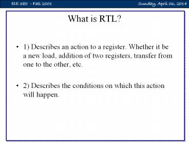
What is RTL?
- 1) Describes an action to a register. Whether it
be a new load, addition of two registers,
transfer from one to the other, etc. - 2) Describes the conditions on which this action
will happen.
2
Guidelines RTL ? hardware
- 1) From the register transfers, determine the
values that should be connected to inputs - If a single input may be set to more than one
possible value, a multiplexer must be used - The exception to the rule above occurs when
all possible inputs come from three-state gates,
and only one possible input is not in the
high-impedance state - 2) From the condition statements, create the
control signals that determine Load, Enable,
Mode, etc.
3
xyT0 T1 yT2 AR ? AR 1
4
Shown below is a 4-bit shift register, R1,
modified from the 8-bit register shown in class.
Show the connections necessary to implement the
following RTL. x R1 ? R1 xy R1 ?
SHR(R1) , R1(A) ? 0 xy R1? SHR(R1) , R1(A) ?
1
What are the conditions for hold? X When x is
true, then inhibit the shift What are the
conditions for shift? xy xy x If y1,
R1(A) 1 If y0, R1(A) 0 Therefore, R1(A)
y
5
5v
6
(No Transcript)
7
Analysis
- Multiplexer enabled when y0Multiplexer output
0 when y1 - x0 selects R2x1 selects R1
- z1 is clearz0 is load
- xyz R5 ? R1 xyz R5 ? R2yz z R5 ? 0
(the same as y z R5 ? 0 )
8
Topics for test 2
- 1) Topics for Test 1
- Gates, MSI circuits, IEEE Standard Notation,
combining smaller circuits to make larger
circuits, ROM, RAM, three-state gates - 2) Representation of integers
- Signed integers, unsigned integers, twos
complement - 3) Integer arithmeticOverflow vs. carry
- 4) Floating point representation
- mantissa and exponent, range, resolution
9
Topics for test 2
- 5) Register Transfer Language
- condition register tranfer
- 6) Arithmetic circuits
- Adder, half-adder, increment
- 7) RTL ? Hardware
- Given an RTL description, generate the hardware
- Given the hardware, generate the RTL description
- Block diagrams and IEEE standard notation


