A1260054075aGTzR - PowerPoint PPT Presentation
1 / 4
Title:
A1260054075aGTzR
Description:
Compare tritium removal from flibe and from Pb-17Li (C. Gentile) Containment concepts to minimize size and shielding (C. Gentile) ... ( C Gentile/R. Raffray) ... – PowerPoint PPT presentation
Number of Views:24
Avg rating:3.0/5.0
Title: A1260054075aGTzR
1
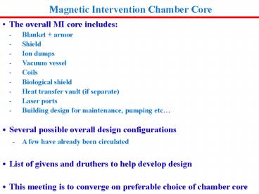
Magnetic Intervention Chamber Core
- The overall MI core includes
- - Blanket armor
- - Shield
- - Ion dumps
- - Vacuum vessel
- - Coils
- - Biological shield
- - Heat transfer vault (if separate)
- - Laser ports
- - Building design for maintenance, pumping etc
- Several possible overall design configurations
- - A few have already been circulated
- List of givens and druthers to help develop
design - This meeting is to converge on preferable
choice of chamber core
2
Givens for HAPL MI Chamber Core
- Beam ports 40, per Malcolms positioning
- Beam port orientation vertical, 61 aspect ratio
- Beam port geometry as worked out by Malcolm and
Mohamed - Field coil cross section 0.8 m x 0.8 m
- Field coils/blanket held by separate entities
- Field coil held by external structure that can
withstand repulsive force (approx. 107 lb for
larger coils, 2 x 10⁶ lb for smaller coils) (Do
these translate to 45 and 9 MN, respectively?) - Chamber radius gt 5 m
- Chamber shape bi-conical
- Blanket thickness sufficient for breeding
- Blanket topology allows low-resistance azimuthal
current path - Vacuum system capable of 1 mTorr or better
- Biological shield cannot be opened for
maintenance - Blanket is not sufficient neutron shield
- Steel/water shield thickness required between
blanket and field coils 0.5 m - Steel/water shield thickness required between
blanket and VV for reweldability 0.3 m - Biological shield thickness required behind
blanket/shield/VV 1.5 m - Biological shield thickness required behind beam
ports 2.5 m - Ion dump ring at equator and pockets at the poles
(Toroidal dump nominally 1 m high, 12.5 m
radius)
3
Druthers for HAPL MI Chamber Core
- Access to blanket does not require re-welding
beam ports - Target injector 15 degrees above bottom dead
center - Chamber radius at mid-plane 6 m
- Blanket thickness 0.7 m at mid-plane increasing
to 1.1 m at top/bottom - Chamber oriented with polar axis vertical
- Access to blanket does not require disconnecting
(or moving) beam ports - Accommodate blanket designs that can be removed
straight up. - Preferred blanket design SiCf/SiC Pb-17Li or
flibe - Field coil positions R3.4 m, Z 5.0 m, R 6.1
m, Z 2.25 (move outward requires increase in
current) - Minimize mass to be lifted for access
- Minimize height of components to be lifted
- Minimize evacuated volume
- Minimize thermal stresses in particular when
attaching components with different operating
temperatures (e.g. blanket to vacuum vessel or
coil to structure) - Design ion dump chambers so as not to affect the
main chamber environment - Position shield (flux conservation boundary) as
far away from blanket to maximize magnetic energy
resistive dissipation in blanket
4
Action Items for HAPL MI Chamber Core
- Compare tritium removal from flibe and from
Pb-17Li (C. Gentile) - Containment concepts to minimize size and
shielding (C. Gentile) - Include all ancillary rooms/vaults in layout
(HTS, Tritium, Pumping, Target Injection) (C.
Gentile/check with M. Sawan on shielding
requirements) - Formalize vacuum pumping system through laser
ports (C. Gentile) - Minimize coil weight and cost (possibility of
using Rutherford configuration (F. Dahlgren) - Temporal and spatial ion energy distribution on
dumps (B. Robson) - Dump design including armor configuration and
maintenance (R. Raffray/G. Sviatoslavsky) - HX material size (R. Raffray/ G.
Sviatoslavsky) - Blanket attachment and maintenance scheme with
smaller opening for both main blanket region and
upper/lower blanket regions (C. Priniski/G.
Sviatoslavsky) - Beam shielding, support and attachment outside
biological shield (G. Sviatoslavsky/M. Sawan) - Thickness of blanket for VV to be reweldable
(M. Sawan) - How to maintain tight fit etween adjacent
blanket modules.use of compliant layer
(Graphfoyl??) (PPPL) - Failure mode effect analysis - check TFTR
experience, others? (C Gentile/R. Raffray) - Assessment of blanket fabrication properties
(SiC/SiC) (L. Snead/ G. Sviatoslavsky)


