Channel Tunnel - PowerPoint PPT Presentation
1 / 6
Title:
Channel Tunnel
Description:
Cross-passages (at every 375 m) to allow access to service ... Generally in dry chalk-marl. 3 km section French side in fractured clay. Ground water saline ... – PowerPoint PPT presentation
Number of Views:219
Avg rating:3.0/5.0
Title: Channel Tunnel
1
Channel Tunnel
2
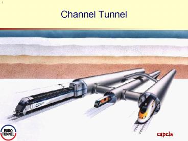
Principle Components
- Tunnel Structure
- Main running tunnels, 2 no. 7.6 m dia
- Service tunnel, 4.8 m dia
- Cross-over caverns (2 no.)
- to allow limited service during maintenance
activities - Piston relief ducts (at every 200 m)
- to allow pressure equalisation
- Cross-passages (at every 375 m)
- to allow access to service tunnel in case of an
emergency, and - provide ventilation and maintenance access
3
Principle Components
- Drainage System
- 5 pumping stations
- Drainage pipework
- Electricity communications
- Supply to caternaries (25 kV)
- Internal lighting and ventilation systems
- Voice Data communications
- Ancillary services
- Cooling system
- Fire-fighting system
- Ventilation system
- Track Traction System
- Running track directly connected to concrete base
slab - Catenaries supported from tunnel crown
4
Environmental Conditions
- External
- Generally in dry chalk-marl.
- 3 km section French side in fractured clay
- Ground water saline
- Internal
- Nominally dry (rh 60 to 99)
- Running Temperature - without cooling 65ºC
- - with cooling 20-25ºC
5
Tunnel Pipework
- Fire-fighting
- 100 mm dia wet main along both running tunnels
- 250 mm dia wet main in service tunnel
- Wet mains inter-connected at cross passages
- Total capacity 4,000 m3
- Cooling
- 450 mm dia pipework in both running tunnels
- Feed and return
- Total capacity 40,000 m3
- Drainage
- 400 mm dia pipework in service tunnel (up to 4
no) - Under track drainage to sumps at pumping stations.
6
Cooling System Schematic
English Side
French Side
Cooling Pumping Stations
Under Land Section
Under Sea Section


