Sections in Engineering Drawing - PowerPoint PPT Presentation
Title:
Sections in Engineering Drawing
Description:
A PPT presentation on all category of sections practised in Engineering Drawing. – PowerPoint PPT presentation
Number of Views:970
Title: Sections in Engineering Drawing
1
(No Transcript)
2
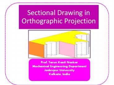
Sectional Drawing
Its a general practice to draw sectional
drawings in orthographic projections. This
provides orthographic projections more clarity
for the purpose of reading an engineering drawing.
All slides are animated. From the next slide
click once at the beginning of each slide and
allow all animations to be performed and then
click for the next slide.
3
Sectional Views
For objects having many internal surfaces, holes,
slots etc., crowding of hidden lines occurs in
normal orthographic views.
These hidden lines make drawings complicated for
interpreting the actual object.
To avoid hidden lines imaginary section planes
are passed in different orientations, internal
surfaces are made visible and then views are
taken.
4
Sectional Views types
Full section
Skin or Local Section
Half section
Offset section
Aligned section
Revolved Removed section
5
Passing Sectional Plane
Full Sectional Front View Top View
Areas of the object that collides with the
cutting plane
Object after section
Full Sectional Front View
Throw away the front part
Thickened at two ends
A
A
Cutting plane A
Top View
6
Full Sectional F-View
Hatch lines on surfaces collided with cutting
plane
7
Hatch Orientations
Parts of a same object with same hatch
orientation
Parts of different objects with different hatch
orientations
8
Hatch Patterns
Different hatch patterns based on materials of
objects as per AutoCAD
9
Full Sectional Front View
Sectional F-View
Thickened at two ends
Front View
T-View
10
Half Sectional Front View
Half Sectional Front View
Quarter of the object sectioned out
Front
Top View
11
Offset Section
Cutting plane lines
Remove the part of the object in front of the
cutting plane
Cutting plane passes in a jig jag manner
12
Offset Section
The rear part
after removal of the front part
take front view
13
Offset Section
Cutting plane lines
Thickened at two ends
Thickened at two ends
Top View Sectional Front View
14
Revolved section if drawn inside
Removed section if drawn outside
REVOLVED REMOVED Sections
15
ALIGNED SECTION
A
Aligned section (A-A1)
Sectional side view drawn as if OA1 is rotated
along with the arm through which it passes to
make it collinear with OA
O
Armed Pulley
Section (A-A1)
A1
Aligned section (A-A1)
16
Skin or Local Section
Skin sections
Cotter Joint
17
Section in Ribs ?
hatch line in ribs omitted
Front
Ribs
Front View
18
Omission of Longitudinal Section
Objects whose longitudinal sections are not drawn
are shafts, keys bolts, rivets, screws, studs,
gear teeth, ribs, rolling elements of bearings
(ball, roller, needle) etc. However, cross
sections are drawn if needed.


