Tevatron Beam Position Monitor Upgrade - PowerPoint PPT Presentation
1 / 19
Title:
Tevatron Beam Position Monitor Upgrade
Description:
Old Tevatron BPM electronics was not accurate, precise or reliable enough for ... Digitize at 74 MHz (synchronous to 53.1 MHz RF). Reasons for the choice: ... – PowerPoint PPT presentation
Number of Views:72
Avg rating:3.0/5.0
Title: Tevatron Beam Position Monitor Upgrade
1
Tevatron Beam Position Monitor Upgrade
- Stephen Wolbers
- (for the Tevatron BPM Upgrade Project)
- PAC05, Knoxville, TN
- May 16-20, 2005
2
Outline
- Motivation for Tevatron BPM Upgrade
- Tevatron BPM Upgrade Design and Implementation
- Performance of New BPM System
- Conclusions
3
Motivation for Upgrade
- Old Tevatron BPM electronics was not accurate,
precise or reliable enough for the Tevatron, nor
was it able to measure pbar positions. - Old system was built in the early 1980s and is
showing its age. - Resolution was 150 microns.
- Uses old networking/controls protocols.
- No pbar position measurements.
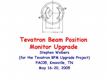
- Pickups in the tunnel not to be modified!
- Directional, 26dB isolation, can be read out from
both ends.
4
Upgrade Requirements
- Stable, accurate, precise measurements.
- Aiming for lt10 micron (1 sigma) precision for
best proton position measurement. - Turn-by-turn (wide-band) and closed orbit
(narrow-band) position measurements. - And safe mode to find the beam when timing is
not well-established after shutdowns. - Software to collect and use the data.
- Reliable hardware and software.
- Measurement of antiproton positions (new
capability). - Requires that both ends of pickups be
instrumented (twice as many electronics
channels).
5
Upgrade System Design
- Position measurement
- The 53 MHz component of the BPM signal is used to
measure the beam transverse position. - Analog signal
- The analog signal is filtered and attenuated on a
special purpose filter board. The bandpass
filters are centered at 53 MHz with width of 8
MHz. - An impulse response time of 400ns was required to
allow for pbar measurements using timing (rather
than proton signal subtraction). - See Poster/Paper from Bob Webber for details of
the timing technique (Plan B).
6
System Design
- Digital processing
- The decision was made to use a commercial digital
signal receiver made by the Echotek corporation. - 80 MHz, 14-bit A/D, Graychip DDC, RAM, FPGA.
- Digitize at 74 MHz (synchronous to 53.1 MHz RF).
- Reasons for the choice
- Speed The boards could be purchased quickly.
- Commonality This board was also chosen for the
Recycler, NUMI, transfer line, and Main Injector
BPM upgrades. - Manpower Freed up engineering and technician
time for other parts of the project - See poster/paper from Gustavo Cancelo for
details about digital filtering.
7
Block Diagram signal/processing path
One pair for p, one for pbar
53 MHz
FPGA
Position, Intensity Raw I,Q
FPGA
53 MHz
8
Proton Signals
MVME
BPM VME Subrack in E3 Service Building
Timing Board
Filter Board
Pbar Signals
Echotek
9
Key Project Dates
- 9/22/03 Requirements review
- 12/19/03 Technology choice review
- 3/11/04 Place Echotek Order
- 5/14/04 Electronics Design Review
- 8/6/04 Install prototype crate in Tevatron
- 8/20/04 First Production Echotek boards arrive
- 8/23/04-12/04 Shutdown
- 11/23/04 Install first production system in A3
- 2/7/05 Finish commissioning A3 system
- 2/7/05-5/31/05 Install remaining systems
10
Installation and Commissioning
- An orderly replacement of the old BPM electronics
was required for operation of the Tevatron. - VME subracks were installed one by one, affecting
approximately 8 BPMs each time. - During commissioning a combination of old and new
systems were used to - Close orbits
- Smooth orbits
- This was accomplished by integrating the new and
old data simultaneously into console
applications. - Overall, this worked extremely well!
11
Installation And commissioning Status Through May
12, 2005
12
Upgraded System Performance
- Overall the upgraded system is working quite
well. - The next few slides will show some examples of
closed orbit, TBT, and pbar measurements. - Position is calculated by
- P 26.(A-B)/(AB) offsets
- Where A and B are the response of the two plates
- 26. is a scale factor for this geometry
- The scale factor and higher order terms may be
refined and added as needed
13
Orbit differences Comparison of two stores at
tuneup
400 mm
Orbit differences of 100 mm clearly seen
F
A
B
C
D
E
14
Correlation of BPM positions and CDF
vertex Measurements at the level of 10-30 mm
CDF Vertical Vertex Pos.
50 mm
Vertical BPM
Some of the imperfect correlation could be due
to Pbar contamination of p measurements or some
geometrical effect
15
Pbar Measurements
Cancellation of proton contamination on Pbar
cables
a,b,c,d determined empirically using the opening
of the helix. Using corrected values, compute sum
and position as for protons. See Rob Kutschkes
poster for details.
p
Pbar
16
Turn by Turn Measurements
1.1 mm full vertical scale
0.6 mm full vertical scale
- Injection TBT 150 GeV 8192 turns.
- One coalesced bunch. HEP shot after all tuning.
17
Fourier Transform of TBT Measurements
1113 / 5 Artifacts
Bin Size 3 Hz Resolution 0.3 mm/sqrt(Hz)
Betatron Lines
Synchrotron Line
18
TBT Detail Synchrotron lines
- Synchroton line present in H but not V.
- 150 GeV expected sync frequency 80 Hz.
19
Conclusions
- The Tevatron BPM Upgrade IS successfully
installed and commissioned. - Work continues on final calibration, diagnostics,
pbar measurements, documentation. - Initial results on precision, stability and
reliability are very promising. - The successful BPM upgrade is a result of the
work of many people in the Computing and
Accelerator Divisions at Fermilab.


