Circuit Timing - PowerPoint PPT Presentation
Title:
Circuit Timing
Description:
SOP implementation: No static 0 hazard Possible static 1 hazard POS implementation (by similar analysis): No static 1 hazard Possible static 0 hazard Static 0 Hazard? – PowerPoint PPT presentation
Number of Views:60
Avg rating:3.0/5.0
Title: Circuit Timing
1
Circuit Timing
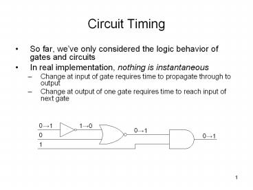
- So far, weve only considered the logic behavior
of gates and circuits - In real implementation, nothing is instantaneous
- Change at input of gate requires time to
propagate through to output - Change at output of one gate requires time to
reach input of next gate
2
- Digital circuits operate in distinctive steps
- Apply inputs to circuit
- Wait for outputs to react
- Sample outputs at circuit
- The speed of this process is determined by a
clock pulse signal (often simply called a clock) - Circuits require a fixed time to respond to their
inputs its important that circuits generate
correct outputs in the alloted time - Being late is as bad as being wrong!
How fast can this circuit be clocked if each
gate has a delay of 5ns?
20 5ns 100ns
1 / 100ns 10MHz
What if each gate has a delay of 50ps?
20 50ps 1ns
1 / 1ns 1GHz
3
Timing Diagrams
4
- In general, for a particular gate, tpHL ? tpLH
- Gate delays vary with operating conditions
- Operating voltage
- Temperature
- Output capacitance
- Therefore, IC designers typically specify
- Minimum delay best case (not very useful!)
- Maximum delay worst case
- Typical delay normal operating conditions
- Often, well use tp max(tpHL, tpLH) for
simplicity
5
Multiple paths from input to output
Assume all rising and falling gate delays are 1ns
The overall circuit delay depends on the
transition path taken from the inputs to the
output
6
Bi-Stable Circuit Ring Oscillator
This circuit is bi-stable
This circuit is known as a ring-oscillator
Assume all gate delays are 1ns
7
In Class Exercise
If A 1, B 1, D 0, and assuming all gates
have rising and falling delays of 1ns, find
and
8
Hazards
- Compare
- Steady-state behavior how a circuits outputs
respond to inputs after input values have been
stable for a long time - Transient behavior the circuit response in the
time between the application of inputs and
steady-state - Problematic transient behavior
- Static Hazard Output that should not change
briefly does - Dynamic Hazard Output that should change once
changes multiple times
9
Static Hazards
- Are static hazards really a problem?
- Synchronous systems (output sampled at fixed
intervals) - Not really slow down clock such that only
steady-state outputs are observed - Asynchronous systems (output continuously
monitored) - Hazard will be interpreted as information!
We need to understand how to detect static
hazards and how to fix them
Hazard!
10
- Static Hazard One input changing causes
glitch when output is not expected to change - Static 1 Hazard Output is expected to remain 1
- Static 0 Hazard Output is expected to remain 0
- SOP implementation
Static 1 Hazard?
Static 0 Hazard?
- POS implementation (by similar analysis)
- No static 1 hazard
- Possible static 0 hazard
- SOP implementation
- No static 0 hazard
- Possible static 1 hazard
11
Using K-maps to locate and correct static hazards
- Key observation Hazard can occur when input
transition causes one product term to switch off
and another to switch on - In K-map terms, this means switching from one PI
to another!
- How to prevent hazards?
- Must add product terms that will remain 1 during
hazard transitions - Add consensus term that we worked hard to remove!
12
In Class Exercise
- List all hazards for the following K-map and
minimal SOP. Then write a new SOP for the same
function that is hazard free.
Hazard-free SOP


