Chap' 5 Registers and Counters - PowerPoint PPT Presentation
1 / 13
Title:
Chap' 5 Registers and Counters
Description:
register consists of a set of flip-flops and gates that ... A:augend. B:addend. Z:carry input. Shift=1,clock enable. 10. Shift register with parallel load ... – PowerPoint PPT presentation
Number of Views:134
Avg rating:3.0/5.0
Title: Chap' 5 Registers and Counters
1
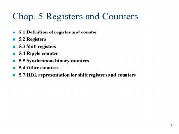
Chap. 5 Registers and Counters
- 5.1 Definition of register and counter
- 5.2 Registers
- 5.3 Shift registers
- 5.4 Ripple counter
- 5.5 Synchronous binary counters
- 5.6 Other counters
- 5.7 HDL representation for shift registers and
counters
2
5.1 Definition of register and counters
- Flip-flip one bit storage element
- register consists of a set of flip-flops and
gates that implement their state transition - n-bit register n flip-flops are included
- counter
- a register that goes through a predetermined
sequence of states upon the application of clock
pulses - registers and counters
- sequential functional block which are used in the
design of digital systems in general and digital
computers - registers storing and manipulating information
- counters sequence and control operations
3
5.2 Registers
Register constructed with 4 D-type flip-flops
common Clock input(rising edge trigger) D input
4-bit binary data Clear input clear a register
to all 0s loading transfer of new information
into a register (load all 4 D inputs into the
flip-flop in parallel)
4
Register with parallel load
- Most digital system master clock generator
- clock gating clock pulses are prevented from
reaching the register when its contents are not
to be changed - load control input Load
- clock is turned on and off at C input by clock
gating in Fig. 5-1(d) - clock gating technique
- clock skew
- inserting gates in the clock pulse path
propagation delay - clock signals arrive at the flip-flops or
registers at different times
C inputs Load Clock
Load1, pulses and edges appear Load0, constant 1
5
5.2 4-bit register with parallel load
Load control input
Load1,data transferred into register Load0,data
inputs are blocked output is remained by
feedback
gt clock pulses are applied continuously
6
5.3 Shift registers
- A register capable of shifting its stored bits in
one or both directions - a chain of flip-flops in cascade output
connected to the input of the next flip-flop - all flip-flops receive a common clock pulse
activate the shift
SI serial input to the leftmost
flip-flop SOserial output of the rightmost
flip-flop
Shift can be controlled by clock gating or input
control
7
Serial transfer
- serial transfer( Parallel transfer)
- information is transferred one bit at a time by
shifting the bits - shift registers are used for the serial transfer
- Shift clock gating
- determination when and how many times the
registers are shifted
Each shift register has 4 states each positive
transition causes the shift
8
Example of serial transfer
9
Serial addition
- Time-space trade-off in design between serial and
parallel - serial adder
- n-bit parallel adder need n full adder
- serial adder 1 full adder, 2 shift register
Aaugend Baddend Zcarry input Shift1,clock
enable
10
Shift register with parallel load
- Converting incoming parallel data to outgoing
serial data - serial communication(transmitterparallel-to-seria
l conversion)
Shift Load Operation
0 0 No change 0 1
Load parallel data 1 x Shift
down from Q0 to Q3
11
Bidirectional shift register
- Unidirectional shift register shift only one
direction - Bidirectional shift register shift both
directions
Mode control Register S1 S0
operation
0 0 No change 0
1 Shift down 1 0
Shift up 1 1 Parallel
load
12
5.4 Ripple counter
- counter
- a register that goes through a prescribed
sequence of states upon the application of input
pulses - input clock pulse fixed intervals of time or
random intervals - binary counter
- a counter that follows the binary number sequence
- n-bit binary counter 0 2n-1
- two categories
- ripple counter
- the flip-flop output transition serves as a
source for triggering other flip-flops - synchronous counter
- C inputs of all of the flip-flops receive the
common clock pulse - the change of state is determined from the
present state of the counter
13
4-bit ripple counter using JK flip-flop
Q(i1) is to be complement when Q(i) change 1
to 0 down counterusing positive-edge-triggered
FF (Q(i1) is changed when Q(i) change 0 to
1) gt C input is normal


