Overview - PowerPoint PPT Presentation
1 / 17
Title:
Overview
Description:
Three planes of diamond sensors (8 mm x 8 mm) Total length 20 cm ... modular cassettes. rides on carriage in rails. parallel to pixel rails. May 2, 2005 Review ... – PowerPoint PPT presentation
Number of Views:10
Avg rating:3.0/5.0
Title: Overview
1
Overview
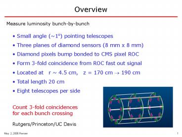
Measure luminosity bunch-by-bunch
- Small angle (1o) pointing telescopes
- Three planes of diamond sensors (8 mm x 8 mm)
- Diamond pixels bump bonded to CMS pixel ROC
- Form 3-fold coincidence from ROC fast out signal
- Located at r 4.5 cm, z 170 cm ? 190 cm
- Total length 20 cm
- Eight telescopes per side
Count 3-fold coincidences for each bunch
crossing
Rutgers/Princeton/UC Davis
2
Detector Features
- Only tracking device with data
- on every bunch crossing
- Stand alone detector
- independent of CMS trigger
- independent DAQ
- Simple device
- 48 sensor planes/channels
- Simple geometry
- 3 planes in coincidence
- Self calibrating
- self monitoring of backgrounds
in pixel mode
- self monitoring of efficiency
- Unfolding of physics/background
- over large range in luminosity
3
Purpose
- Luminosity measurement
- precise, stable measurement of relative
luminosity
- normalize to W Z production
- normalize to ?tot at L 1028 cm-2s-1
- CMS Trigger/detector acceptance
- provide reference standard by which to monitor
- trigger and detector responses
- Determine intensity of individual bunch
interactions
- event overlay selection in MC
- effect of trigger bias
- Beam diagnostics
- Measure uniformity of bunch-to-bunch intensity
- Measure location of IP
- from pixel readout
- Determine hot spots
- on-line display
- Measure beam halo
4
CMS Pixel Readout Chip
CMS pixel chip has fast multiplicity counting
built in
active area
80 x 52 pixels
100 ?m x 150 ?m
8 mm
Fast output level (each bunch crossing)
- 0, 1, 2, 3, ? 4 double column hits
- individual pixel thresholds adjustable
- individual pixels can be masked
8 mm
Full pixel readout (every L1 trigger)
- pixel address and pulse height of each hit
- diagnostic of fast out signal
IP Scattering Beam halo
- determination of track origin
- determination of IP location
5
Single Crystal (SC) CVD Diamond
- Radiation hard (few x 1015 cm-2)
- No need for cooling
- Full charge collection at 0.2 V / ?m
- 15,000 e? for 400 ?m diamond
- Landau 60 narrower than Si
- Availability of 8 mm x 8mm pieces
- 2 pieces end of last year
- 8 pieces in May/June
- ready for production by end of year
This summer at Fermilab test beam
- Test performance of irradiated
- diamond pixel detectors
- efficiency
- spatial resolution
Ready to place order in Fall
- radiation hardness
6
Radiation Levels
hadrons
all charged
- signal x 1.5
neutrons
- electrons x 1/2
- neutrons x 1/2
signal to background
improved by factor of 3
plots from M. Huhtinen
7
Location
- End of Be section of beam pipe ( 1.7 m from IP)
- Just outside of beam pipe ( 4 cm from beam line)
IP
Luminosity telescopes
8
Support Structure
support frame
telescope support
rides on carriage in rails parallel to pixel
rails
telescopes installed as modular cassettes
Complete design by end of summer
9
Preliminary Structure For testing gt Needs
independent rail system
10
BCM1 and BCM2 locations
11
(No Transcript)
12
Bump Bonding
- Bumping of readout chips
- done at PSI as part of pixel project
- Metallization of diamond
- Ti/W pixel electrodes, capability at Rutgers
- Bumping of individual diamond pieces
- UC Davis has successfully done this in the past
- Flip chipping
- UC Davis has capability
- Total of 48 pieces need to be bump bonded
- 100 pixel yield not required
- Diamond sensor can be reworked if bumping fails
13
Rate Simulations
Hits per bunch crossing for
Luminosity 1034 cm-2 s-1
Per telescope
Per array
singles rate
3-fold coincidence
3-fold coincidence
Pythia (no B field)
0.32
0.26
4.1
Pythia (with 4T field)
0.38
0.25
4.0
Pythia full simulation
0.63
0.27
4.3
- Beam pipe
- Full CMS geometry
- 4T field
10 of coincidence rate due to background
40 of singles rate due to background mostly
electrons produced from ?s interacting on beam
pipe
14
Acceptance
telescope arrays both sides
telescope array one side
beam pipe r 3.0 cm
z 1m
z 1m
acceptance vs. z at r0
acceptance vs. r at z0
? 3?
beam pipe r 3.0 cm
15
IP Precision
curvature in 4T field
pixel width 100 ?m x 150 ?m
? ?r 50 mm / p(GeV)
? ?? 40 ?m hit resolution
?z 200 cm / p(GeV)
?r 1 mm
?r 0.5 mm
at p 50 GeV
at IP
?z 4 cm
?z 2 cm
100k tracks in 1 s
?r 10 ?m
In one second centroid of IP location precision
?z 400 ?m
- simple fitting of tracks
Detailed simulation for June Review
- online display
16
Beam Halo
101 aspect ratio
fraction of area sensitive to horizontal tracks
32
plane 3
mask this area if necessary
plane 2
plane 1
20 cm
For 30 cm long telescope insensitive but solid
angle reduced by 10
plane 3
plane 2
plane 1
30 cm
17
Performance Capability
- Measure 4 tracks per bunch crossing at full
luminosity
Determination of relative luminosity of each of
3568 bunches within an orbit to 1 over 1 s (104
orbits)
keep running 3568-channel histogram of bunch
crossings within orbit
- IP determination ?r 10 ?m ?z 400 ?m
in 1 s
Detailed map of particle source in real time
- Sensitive to horizontal tracks
Determine amount of beam halo
if background to luminosity measurement, mask
pixels


