Instruction Fetch Stage - PowerPoint PPT Presentation
1 / 38
Title:
Instruction Fetch Stage
Description:
The temp2 register is loaded with instruction and taken PC part of the IF/ID2 in ... Out1 corresponds to BTB fetch-index being, the PC register. ... – PowerPoint PPT presentation
Number of Views:32
Avg rating:3.0/5.0
Title: Instruction Fetch Stage
1
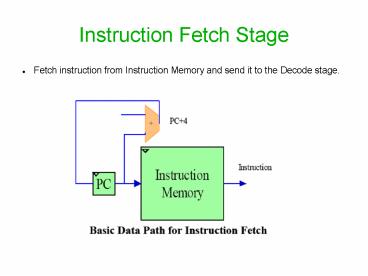
Instruction Fetch Stage
- Fetch instruction from Instruction Memory and
send it to the Decode stage.
2
Instruction Fetch Stage
3
Whats New ?
Assume sub a0,3,4 is stored
- Store the branch target
- Loop
- beq 5,5,Label
- add a0,3,4
- ....
- ....
- Label
- sub a0,3,4
- add a1,8,9
Instruction Fetch
Instruction Decode
beq 5,5,Label X
add a0,3,4 beq 5,5,Label
Sub a0,3,4 STALL
add a1,8,9 sub a0,3,4
4
Whats New ?
Assume sub a0,3,4 is stored
- Store the branch target
- Loop
- beq 5,5,Label
- add a0,3,4
- ....
- ....
- Label
- sub a0,3,4
- add a1,8,9
Instruction Fetch
Instruction Decode
beq 5,5,Label X
add a0,3,4 sub a0,3,4 beq 5,5,Label
add a1,8,9 sub a0,3,4
BTB Cache (sub a0,3,4)?
5
Stalls !
- Stalls are very common due to Branch or Data
hazards. - Branch Hazards
- 1 clock cycle penalty for the current MIPS
architecture to calculate target address. - In many applications looping or branching occurs
very frequently. - Ex
- for (i0ilt100i)?
- Label1
- Label2
6
IF stage with BTB Architecture
7
Why these many registers ?
Assume sub a0,3,4 is stored
- Store the branch target
- Loop
- beq 5,5,Label
- add a0,3,4
- ....
- ....
- Label
- sub a0,3,4
- add a1,8,9
Instruction Fetch
Instruction Decode
beq 5,5,Label X
add a0,3,4 sub a0,3,4 beq 5,5,Label
add a1,8,9 sub a0,3,4
BTB Cache (sub a0,3,4)?
8
BTB Read
- Assume entries for branches are
- already in the BTB Cache
- Sequence should be
- Loop
- B1
- B3
- A1
- A2
- B2
- B4
9
BTB A register level look !
10
General Flow of registers any clock cycle
- The temp2 register is loaded with instruction and
taken PC part of the IF/ID2 in previous cycle. - The IF/ID1 register is loaded with instruction
corresponding to address in PC register in
previous cycle. - The instruction to be decoded will be selection
of IF/ID1 or temp2. If previous instruction is
branch and taken then temp2 is selected else for
non branch instruction or branch but not taken
instructions, IF/ID1 is selected. - IF/ID2 is written with either Out1 or Out2. Both
entries comprise of taken instruction, taken PC,
taken PC4. Out2 is selected if instruction
decoded in previous cycle is branch and taken,
else Out1 is selected. - PC is updated with either PC4 or taken PC4. If
the instruction decoded in previous cycle is
branch and is taken then taken PC4 is chosen
else if it is not a branch or branch but not
taken, then PC4 is chosen. - Out1 corresponds to BTB fetch-index being, the PC
register. - Out2 corresponds to BTB fetch-index being, the
taken PC of IF/ID2 register.
11
tick1
A1
X
B1
X
B3
X
X
X
X
12
tick2
A2
B1
A1
B1
X
B3
X
B4
A1
13
Flow - Example
Control
14
tick3
A4
A1
B4
B3
B1
A1
B3
A2
X
15
Flow - Example
Control
16
tick4
B2
B4
A2
A1
X
X
A1
X
X
17
Flow - Example
Control
18
tick5
A3
A2
B2
A2
B4
X
X
X
X
19
Flow - Example
Control
20
tick6
B3
B2
A3
B2
X
B4
X
A4
B1
21
Flow - Example
Control
22
tick7
X
A3
A4
B4
X
B1
B4
A1
B3
23
Flow - Example
Control
24
tick8
A2
A4
A1
B1
X
B3
B1
B4
A1
25
Flow - Example
Control
26
tick9
A4
A1
B4
B3
B1
A1
B3
A2
X
27
Timing
28
BTB Write
29
Control Logic
30
Control Logic
31
Control Logic
IsBTBWrite is a delayed version of Write signal
32
Memory Load Logic
33
Simulation using ModelSim
34
Results
35
Placing and Routing
36
Possible Improvements
- Using Flips flops with enable signal (pc_stall)
could reduce the control logic complexity as well
as negative edge registers are no more required
(whose purpose is to retain previous cycle
contents). - The BTB entry takenPC4 is redundant. A -4 adder
could suffice for the solution.
37
IF stage with BTB Architecture
38
References
- Reducing Misprediction Penalty in the Branch
Target Buffer Sherine AbdelHak, Abhijit Sil, Yi
Wang, Nian-Feng Tzeng, Magdy Bayoumi. Circuits
and Systems, 2007. MWSCAS 2007. 50th Midwest
Symposium Publication Date 5-8 Aug. 2007 - Hennessy J., Patterson D., Computer
Architecture, A Quantitative Approach, Morgan
Kaufmann, 2003.


