PS-TuP8 - PowerPoint PPT Presentation
1 / 1
Title:
PS-TuP8
Description:
Designed and simulated using Ansoft Ensemble. 900 MHz: f = 20 mm, ... This work is supported by the National Science Foundation under Grant No. CCF-0403460 ... – PowerPoint PPT presentation
Number of Views:32
Avg rating:3.0/5.0
Title: PS-TuP8
1
PS-TuP8 Frequency and Dimensional Scaling of
Microplasmas Generated by Microstrip Transmission
Lines Istvan Rodriguez, Jun Xue, and Jeffrey
Hopwood, Northeastern University Boston, MA 02115
0.9 GHz Results
1.8 GHz Results
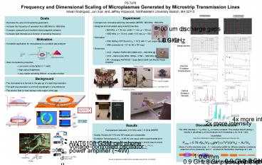
- Experiment
- Compare two microstrip split-ring resonators
(MSRR) 900 MHz, 1800 MHz - Designed and simulated using Ansoft Ensemble
- 900 MHz f 20 mm, width 1 mm, g 100 um.
- 1800 MHz f 10 mm, width 0.5 mm, g 100 um.
- Fabrication
- CNC Milling of RT/Duroid (eR 10.2) with 17 mm
copper cladding - SMA connector at 12 for 50 W RF input
- Electronics
- VCO Raltron RQRA 0810-0900 (810 900 MHz _at_
2dBm) - VCO Minicircuits MOS-1825pv (1766 1826 MHz _at_
2dBm) - PA Anadigics AWT6108 Quad Band GSM Cell
Phone Power Amplifier
- Goals
- Decrease the size of microplasma generators
- Increase the frequency of operation from 900 MHz
to 1800 MHz - Compare measured and modeled electromagnetic
behavior - Compare light intensity as a function of
operating frequency
100 um discharge gaps
EM Model
1.8 GHz
0.9 GHz
- Motivation
- A possible application for microplasma is a
portable gas analyzer - Ideal microplasma properties
- Low power consumption (lt 1 watt)
- High optical brightness
- Long, stable operating lifetime no sputter
erosion
EM Measurement
VCO
Electron Excitation Temperatures
Power Control
MSRR
- Background
- The microplasma is formed in the gap (g) of a
split-ring resonator - The split-ring resonator is one-half wavelength
in circumference - The electric field is most intense in the region
of the gap
Power Amplifier
Low Band VCO
Frequency Control
Optical Emission Intensity
10 mm
900 MHz in 1 atm. air
argon
4x more intensity!
2x more intensity
100 um gap _at_ 1W ? 1 MV/m
Discussion and Conclusion The OES intensity I
ne since Texc is nearly constant. This implies
that doubling w results in doubling ne at low
pressure and increasing ne by 4x at 1
atm. Hypothesis Simple Ohmic Heating Model for
Capacitive Discharges (Lieberman and Lichtenberg,
p. 344) Pohm ? 0.76 Aeo2menmg/e2 (w2V2)/(s2ne)
Aw2/ne where A is the electrode area A
(microstrip width) for diffusive plasma
conditions observed at low pressures, but A
constant for filamentary discharge at 1 atm
- Results
- Comparison between 0.9 GHz and 1.8 GHz MSRR
- Quality Factors (Q170) and RF losses are
comparable - Excitation Temperatures (Texc0.65 eV) are equal
within experimental error - Optical Emission Intensity is several times
higher at 1.8 GHz than 0.9 GHz - emission intensity is proportional to electron
density, I ngas K(Te) ne - increasing the frequency also increases the
electron density
1 mm
0.5 mm
1.8 GHz (high pressure)
0.9 GHz (high pressure)
0.9 GHz (low pressure)
1.8 GHz (low pressure)
ne?4ne
ne?2ne
This work is supported by the National Science
Foundation under Grant No. CCF-0403460


