Robot Kinematics - PowerPoint PPT Presentation
1 / 29
Title:
Robot Kinematics
Description:
Coordinate Transformation Matrix (CTM): Relationship between two ... verified that the transpose of R matrix is its inverse matrix. ... The matrix T has the ... – PowerPoint PPT presentation
Number of Views:151
Avg rating:3.0/5.0
Title: Robot Kinematics
1
Robot Kinematics
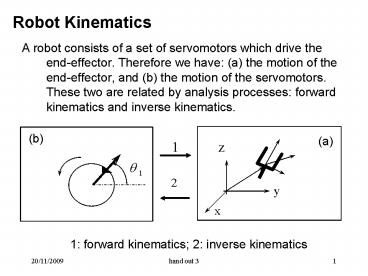
- A robot consists of a set of servomotors which
drive the end-effector. Therefore we have (a)
the motion of the end-effector, and (b) the
motion of the servomotors. These two are related
by analysis processes forward kinematics and
inverse kinematics. - 1
z
(b)
(a)
2
y
x
1 forward kinematics 2 inverse kinematics
2
- There are two coordinate systems for measuring
the two types of motions - - motor coordinate system
- - world coordinate system
- 2.2 Description of position and orientation
- Description of the motion of motor is easily done
in the motor (or joint) coordinate system for
each individual motor (see Fig.2-11). - Description of the motion of arm and end-effector
will be done in the world coordinate system -
attach a coordinate system on a body (see
Fig.2-12).
Related, how?
3
- Motor motion
- CCW -gt positive angle
- End-effector motion
Figure 2-11
Figure 2-12
4
Attached coordinate system
- The relationship of the attached coordinate
system with respect to the world coordinate
system completely describes the position and
orientation of that body in the world coordinate
system (Fig. 2-13).
5
Attached coordinate system
Attached coordinate system (also called local
coordinate system) replaces the object and
represent it with respect to the world coordinate
system or reference coordinate system
The motion of the object with respect to the
reference coordinate system reduces to the
relation between the local coordinate system with
respect to the reference coordinate system
6
Attached coordinate system
- The A and B relation is denoted by Ref (A-B)
- Suppose A is a local coordinate system of the
object and B is a reference coordinate system - By defining A on the object, we imply that
details of the object are defined - The details of the object with respect to B
need to be found in order to understand the
motion of the details of the object with respect
to B
7
- Key questions
- The relation between two coordinate systems, A
and B - The representation of Point P (which is defined
in Frame A) in Frame B given Rel (A-B)
8
Coordinate Transformation Matrix
(CTM) Relationship between two coordinate systems
Key Question 1
9
- Remark Motion is also related to velocity and
acceleration. The general idea is that they
should be obtained by the differentiation of the
transformation matrix. - 2.3 CTM
- Let A and B are two coordinate systems at the
same location see the figure in the next slide.
We consider representing B in A.
10
(No Transcript)
11
Unit vectors giving the principal directions of
B as When these vectors written in terms of
A, we have Stack these three together, and
call rotation matrix (2-1)
12
Equation (2-1) can be further written as
(2-2) The components in equation
(2-2) are simply the projections of that vector
onto the axes of its reference frame. Hence, each
component of equation (2-2) can be within as the
dot product of a pair of unit vectors as
To be given in the classroom
To be given in the classroom
(2-3)
13
A with respect to B ?
To be given in the classroom
B with respect to A
14
The inspection of equation (2-3) shows that the
rows of the matrix are the column of the
matrix as such we have
(2-4)
To be given in the classroom
It can be further verified that the transpose of
R matrix is its inverse matrix. As such, we have
(2-5)
15
When frame A and frame B are not at the same
location (see Fig. 2-14), we have the following
representation
Representation of the origin of B in Frame A
16
Fig. 2-14
17
Further, if we have three frames, A, B, C, (Fig.
2-15) then we have a chain rule such that (see
the figure in the next slide)
18
Fig. 2-15
19
2.4 Key Question 2 Point P at different frames
Fig. 2-16 shows that the same point, P, is
expressed in two different frames, A and B.
P
Fig. 2-16
20
Case 1 Frame A and Frame B are in parallel but
at different locations (see Fig. 2-17)
Fig. 2-17
In this case, we have the following relation
21
(2-7)
in A in B
Case 2 A and B are at the same location but with
different orientations (see Fig. 2-18). In this
case, we have
(2-8)
22
Fig. 2-18
23
Example 1 Fig.2-19 shows a frame B which is
rotated relative to frame A about
is an axis perpendicular to the sheet plane
- Please find
- Representation of Frame B with respect to
Frame A - Representation of P with respect to Frame A
24
Fig. 2-19
10
30o
25
Solution
To be given in the classroom
26
See Fig. 2-18, A and B are at different locations
and with different orientations
We have
(2-9)
We can further write equation (2-9) into a
frame-like form, namely a kind of
mapping (2-10)
The matrix T has the following form
27
To be given in the classroom
(2-11)
Example 2 Fig.2-20 shows a frame B which is
rotated relative to frame A about Z by 30
degrees, and translated 10 units in XA and 5
units in YA. Find where
28
Fig. 2-20
YB
YA
P (3, 7, 0)
XB
30o
5
XA
10
29
Solution
To be given in the classroom


