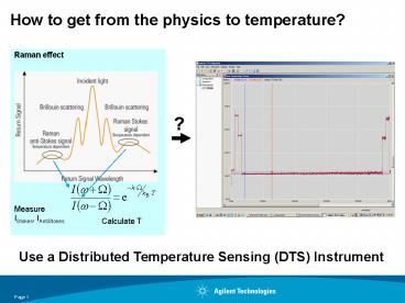
How to get from the physics to temperature - PowerPoint PPT Presentation
1 / 27
Title:
How to get from the physics to temperature
Description:
2) Lower pulse rate reduces energy launched into the fiber ... resolution setting means longer pulse width. A longer pulse increases the energy launched into ... – PowerPoint PPT presentation
Number of Views:29
Avg rating:3.0/5.0
Title: How to get from the physics to temperature
1
How to get from the physics to temperature?
?
Use a Distributed Temperature Sensing (DTS)
Instrument
2
How Temperature Resolution is Impacted
- Fiber length impacts Signal to Noise
- 1) Temperature resolution degrades along the
length of a fiber because - the incident and backscattered signal are
attenuated reducing Signal to Noise - 2) Lower pulse rate reduces energy launched into
the fiber - Longer measurement time provides more data to
average - Averaging data reduces random noise providing
better Signal to Noise - Higher spatial resolution setting means longer
pulse width - A longer pulse increases the energy
launched into the fiber which boosts - the backscattered S/AS signal providing
better Signal to Noise - Theory 1m sp res 10ns pulse
3
(No Transcript)
4
(No Transcript)
5
(No Transcript)
6
(No Transcript)
7
(No Transcript)
8
(No Transcript)
9
(No Transcript)
10
(No Transcript)
11
(No Transcript)
12
(No Transcript)
13
(No Transcript)
14
Example with Agilent Calibration Software
15
Calibrating the DTS Instrument to the
SensorAbsolute accuracy (single ended)
The measured absolute temperature values strongly
depend on the individual fiber!
- Without calibration of the sensor fiber specific
parameters - Temperature Offset
- Gain, Attenuation Ratio
- the measured values may differ significantly from
the actual values.
temperature
measured
16
Sensor Calibration
Need to go from -
this
to this
S intensity loss and temperature AS intensity
loss and temperature
17
Sensor Calibration
Offset Calibration
- A single temperature reference point can provide
the data needed
18
Sensor Calibration
Gain Calibration
- Gain is a slope so two separate data points are
needed at two reference temperatures
19
Sensor Calibration
Attenuation Ratio Calibration
Backscatter Stokes and Anti-Stokes for Fiber at T
Constant
1113nm Stokes
Loss (db)
0.25 dB/km
1018nm Anti-Stokes
1 km
distance
- Use a single reference temperature over as long a
section of fiber as possible - Use a 2 point calibration various methods
- Note Assumes Attenuation Ratio is constant
throughout fiber length.
20
Sensor Calibration
Raw Temperature Trace
Temperature
T2real
T1raw
T1real
T2raw
Points with known Temperature
Distance
- DTS instruments have tools so you dont have to
do the math
21
Sensor CalibrationDouble Ended Loop
Stokes, Antistokes
CH 1 to 2
Temperature Loss
0
1000
2000
3000
4000
5000
Fiber loops back to DTS and connects to a 2nd
channel
0
CH 2 to 1
-2
Stokes -gt
-4
AntiStokes -gt
-6
Stokes lt-
-8
AntiStokes lt-
-10
-12
Stokes, Antistokes
Diff AntiStokes - Stokes (linear ratio)
Loss
Temperature
(fiber, connector, bad splice w wavel. dep. Loss)
0
1000
2000
3000
4000
5000
0
1000
2000
3000
4000
5000
0
0
-0.5
-2
-1
-1.5
-4
Stokes -gt
Diff -gt
-2
AntiStokes -gt
Diff lt-
-6
-2.5
Stokes lt-
Ave (Temp)
-3
-8
AntiStokes lt-
-3.5
-10
-4
-12
-4.5
22
Sensor CalibrationSingle Ended no calibration,
attenuation ratio effect
Fiber at constant temperature trace should be
flat
23
Sensor CalibrationDouble Ended no calibration,
attenuation ratio effect eliminated
Fiber at constant temperature trace is flat
24
Sensor CalibrationDouble Ended Loop - Summary
- No need for Attenuation Ratio calibration
- Compensates if attenuation ratio changes over
time and distance - Fiber can be deployed to go out and come straight
back or make a loop - Still may need offset and gain calibration
Note Many times the Gain factor for a fiber
is very close to 1.0. Therefore an offset only
calibration may be sufficient when using a DE
configuration.
25
Misc
- Know the instrument put in place a calibration
strategy - Things to keep in mind that vary on different
instruments - Fiber attenuation sources
- Differential Loss (double-ended,
two-frequencies) - Signal-to-noise (SNR) (photon counting)
- Pulse width/coding (lower powers)
- Forward scattering system (?)
26
Recommendations
- Cal Fiber in Lab
- Examine
- Noise as a function of samples, length
- Simulated field stresses, and recalibration
- Cal Fiber in Field
- Compare field and lab calibration
- Identify stress points
- Place local temperature sensors in sections
between stress points - Get one additional temperature in
these sections (Double-ended) - Get two additional temperatures in
these sections (Single-ended)
27
(No Transcript)


![Modern Physics [2] PowerPoint PPT Presentation](https://s3.amazonaws.com/images.powershow.com/8002705.th0.jpg?_=20160723081)
![L 36 Modern Physics [2] PowerPoint PPT Presentation](https://s3.amazonaws.com/images.powershow.com/7897333.th0.jpg?_=20210302064)


