Potential Swiss Army Knife Applications - PowerPoint PPT Presentation
Title:
Potential Swiss Army Knife Applications
Description:
Size Estimates/Floorplan/Verilog (85% - comb/Wallace alterations) ... Removed in order to prevent unmanageable design size. WALLACE TREE MULT. ... – PowerPoint PPT presentation
Number of Views:100
Avg rating:3.0/5.0
Title: Potential Swiss Army Knife Applications
1
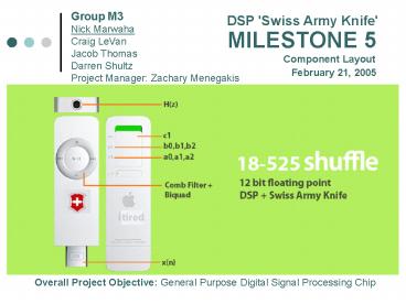
Group M3 Nick Marwaha Craig LeVan Jacob
Thomas Darren Shultz Project Manager Zachary
Menegakis
DSP 'Swiss Army Knife'
MILESTONE 5 Component Layout
February 21, 2005
Overall Project Objective General Purpose
Digital Signal Processing Chip
2
STATUS
- Design Proposal (Done)
- Architecture (Done)
- Size Estimates/Floorplan/Verilog (85 -
comb/Wallace alterations) - Gate Level Design (80 - comb/Wallace
alterations) - Component Layout (Done - However, continue to
optimize) - To Be Done
- Complete layout of functional blocks
- Wallace Tree Multiplier, etc.
- Schematic
- Make remaining adjustments for comb/Wallace
- Verification
- Test for adjusted blocks
3
DESIGN DECISIONS
- Comb
- Removed 8 floating point multipliers and a
multiplexer (about ½ of the comb) - Allows circuit to implement 3 of 4 functions that
require the comb - Transistor count significantly above 25K limit,
however much of the comb is redundant - Use of Wallace Tree Multiplier in place of matrix
multiply - Increases complexity of the design
- Compared between Traditional Wallace Tree and
Wallace Tree with Booth Recoding - Booth Recoding adds partial products in parallel
and reduces space - Chose to use Booth Recoding in order to optimize
space
4
DESIGN DECISIONS
- Porosity of Basic Components
- Using only Metal 1 and Poly in order to ease
global routing - Imaginary Numbers
- Current circuit can only handle real s since
imaginary s require significant additions to an
already large and complex design - Working on what would be necessary possibly
for soft IP
5
DESIGN DECISIONS cont
Now Only 1 Function Removed
Name a0 a1 a2 b0 b1 b2 c1 N
1 Differencer 1 0 0 1 -1 0 0 x
2 Integrator 1 1 0 1 0 0 0 x
3 Leaky Integrator 1 1 0 1 0 0 0 x
4 Comb Filter 1 0 0 1 0 0 1 8
5 Bandpass Filter 1 0 -1 1 0 0 1 16
6 CIC Interpolation Filter 1 1 0 1 0 0 1 8
7 dc Bias Removal 1 a.b 0 1 -1 0 0 x
8 First-Order Equalizer 1 a.b 0 a.b 1 0 0 x
9 Audio Comb 1 0 a.b 1 0 0 0 x
10 Moving Averager 1 1 0 1/N 0 0 1 8
11 Second-Order IIR Filter 1 a.bbb a.bbb a.bbb a.bbb a.bbb 0 x
12 First-Order Delay Network 1 a.bbb a.bbb a.bbb a.bbb 1 0 x
13 Second-Order Delay Network 1 a.bbb a.bbb a.bbb a.bbb 1 0 x
14 Real Oscillator 1 2cos(x) -1 1 0 -1 x x
15 Second-Order Equalizer 1 a.bcos(x) a.b 1 a.bcos(x) 1/a.b 0 x
6
DESIGN DECISIONS cont
Comb Design
Removed in order to prevent unmanageable design
size
7
WALLACE TREE MULT.
Traditional Wallace Tree
Booth Recoding Wallace Tree
8
IMAGINARY NUMBERS
- Modifications for complex arithmetic
- Complex addition
- 2 scalar adds
- Complex multiplication
- 4 scalar mults and 2 scalar adds
- 3 scalar mults and 4 scalar adds
- Complex division
- 8 scalar mults and 4 scalar adds
9
IMAGINARY NUMBERS
- Design and Transistor Count Changes
- with Imaginary Numbers
- Comb
- Div 1 ? 2
- Mults 8 ? 32 or 24
- Adder 1 ? 18 or 38
- Biquad 1 div ? 2
- Mults 6 ? 24 or 18
- Adders 4 ? 20 or 32
- Comb
- 321770 181839 89742 2Divide overhead
OR. - 181770 381839 101,742 2Divide overhead
- Biquad
- 241770 201839 79,260 2Divide overhead
OR - 181770 321839 90,708 2Divide overhead
- TOTAL (ABSOLUTE MINIMUM) 179,002 overhead
- Approximate count 200,000 transistors
10
FLOORPLAN UPDATE
FP Divider
FP Multipliers
FP Adders
FP Divider
FP Adders
FP Multipliers
11
SIZE ESTIMATES
12
COMPONENT LAYOUT
NAND
AND
OR
13
COMPONENT LAYOUT cont
XOR
MUX-2x1
14
COMPONENT LAYOUT cont
FULL ADDER
15
PROBLEMS QUESTIONS
- Full Adder
- Currently using a 24 transistor design
- Pass gate design can reduce size, however
problems with transistor sizing buffering - Problem Timing issues with top level design.
(recursive circuit).


