
Typical Process State Diagram - PowerPoint PPT Presentation
1 / 29
Title:
Typical Process State Diagram
Description:
Key O.S. Functions for Process Handling. Process Creation. ... Periodic execution after certain interval like a Screen Saver. Parent process request. ... – PowerPoint PPT presentation
Number of Views:1337
Avg rating:3.0/5.0
Title: Typical Process State Diagram
1
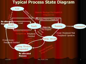
Typical Process State Diagram
New
Memory Shortage Pre-Empted Swapped Out
Admit / Load
Admit
Scheduled THEN Dispatched
No allocated Memory
Load
Ready Suspend
Ready
Running
Terminated
Time Out Pre-Empted
Event Occurs
Memory Shortage Swapped out
Event/ Peripheral Wait / Peripheral Operation
Peripheral Finished
Waiting / Blocked
Memory Available/Activate
Event Occurs / Peripheral Finished
Waiting /Blocked Suspended
Memory Shortage Swap out to Disk
No allocated Memory
2
Key O.S. Functions for Process Handling
- Process Creation.
- Process Admission in Memory Ready Queues
along with Pre Assigned Associated Priority for
each Process. - Process Scheduling Select to Dispatch Next.
- Process Dispatching Allocate CPU.
- Process Pre-Emption Context Switching between
processes very important for Multi Programmed
OR Multi Tasked System supported by various
types of Interrupts Timer Interrupt, Device
Interrupt, Supervisor Call SVC / Software
Interrupt. - Synchronization of Concurrent Processes in a
Multi Tasked Environment which involves enforcing
Memory Resource Sharing Protocols. - Process Termination ( Normal / Abnormal).
- Handling Process request for resources other
than CPU ( Peripheral , Memory) normally done via
Supervisor Call SVC / Software Interrupt. - Process Swapping between Main Memory Virtual
Memory ( Disk Swap Space) on Demand.
3
Process Creation
- State New -gt Any Process is created by the
O.S. in response to user command or by itself .
All processes are first created in the Virtual
Space ( Secondary Memory ) . At any point of
time several user processes may exist so typical
of a Multi- Programmed / Multi Tasked Scenario.
4
Reasons for Process Creation
- New batch job presented to O.S. for execution.
- A new user logs on in an interactive system.
- Created by the O.S. to provide a Service like
the creation of a Print File. - Spawned /Created by any existing process for
purpose of modularity or to exploit Time
Sharing. - e.g. a) User process calling an application
by a command. - b) User process executing a
Process Creation - Call (an SVC) like fork.
- In cases 3. 4. we have a Parent Process
spawning a Child Process.
5
Process Creation Steps 1
- State New -gt Create a new process. This
involves the following - Assign an Unique Process Identifier (PID).
- Allocate Space for the entire Process Image in
the Virtual Memory. Space requirement information
is obtained from - 1) Default based on the process type.
- 2) Specified by user via Job
Specification. - 3) Supplied by the Parent Process.
6
Process Creation Steps 2
- Initialize the Process Control Block (PCB) in
the following manner - 1) Set up the processor state information
- a) Initialize Instruction Pointer Code
Segment Register - to the Code Entry Point.
- b) Initialize Stack pointers to the
relevant stack boundaries. - c) All other registers Flags are
initialised to ZERO.
7
Process Creation Steps 3
- 2) Process Control Information Section is
initialised - based on default values like
- a) Process State New ? Ready (If Memory
Available) - OR New ? Ready / Suspend
otherwise. - b) Lowest priority / Specified at the
time of creation / - Inherited from the parent.
- c) No resources hold except for Disk Swap
Space / - Explicit resource request/ Inherited
from the - parent.
8
Process Creation Steps 4
- Set appropriate linkages / Put in the relevant
Queue (Ready OR Ready/ Suspend). - Create or Expand other data structures like
accounting / system log.
9
Loading a Process into Main Memory
- NEW ? READY OR READY/SUSPEND ? READY
- This involves loading a Process / Its relevant
portion from Files on Disk OR alternately from
Disk Swap Space to Main Memory by the O.S.
Modules involved are File Manager, Memory
Manager , Long Medium Term Scheduler as well as
the Loader . In a Multi programmed / Multi
Tasked environment several user processes gets
loaded and some portions of all of them reside in
the main memory. Needs Block Level DMA based /
Interrupt Driven data transfer. - After coming into memory, all these
Processes lie in Readiness waiting to be executed
by the CPU. These Processes are maintained in
one/ several Priority Queues each of which is
termed as a READY Queue. Each READY Queue is
actually a Queue of Pointers that resides in main
memory. Each of these pointers are pointing to
the relevant / concerned PCBs in main memory. - If no Memory is currently available then the new
Processes are put in the Swap Space - NEW ? READY / SUSPEND
10
Process Scheduling Dispatching
- READY ? RUNNING
- Scheduling Selecting the Process from the set
of Ready Queues to be executed next . Performed
by the Short Term Scheduler based on some
predefined scheduling policy. - Dispatching the Scheduled Process Allocating
the CPU to the scheduled a process i.e. loading
the Code Segment Register as well as the
Instruction Pointer / Program Counter Register of
the CPU with appropriate addresses. Performed by
the Dispatcher/ Short Term Scheduler of the O.S.
After being Dispatched , the Process starts
running/ is being executed by the CPU.
11
Process Pre- Emption Scenario
- Running ? Ready Caused by one of the
following reasons - a) Allotted Time Slice over signaled by
Internally generated Timer Interrupt from the
Programmed Interval Timer. - b) Entry of a High Priority Process ( depends
on the Scheduling Policy ) - Running ? Ready / Suspended. Same reasons as
before in addition Non Availability of Main
Memory due to Higher Memory demand of the next
Scheduled Process.
12
Reasons for Process being Blocked Running ?
Blocked/ Wait
- Requested for Peripheral Service using
Supervisor Call SVC / Software Interrupt
waiting for it to complete. This may include
User Response. - Requested for Peripheral Service using
Supervisor Call SVC / Software Interrupt
waiting for its availability in the respective
WAIT Queue. - Require some sort of message from some other
process Waiting for the arrival of that
Message. - Waiting for the spawned child process(s) to
complete.
13
Running ? Blocked/ WaitAssociated Events
- a) Scheduling Dispatching of a New Process
to prevent CPU idle time. This requires Context
Switching. - b) Mode Switching for the Process going into
the Blocked / Waiting State.
14
Reasons for process suspension / Swapped out of
Memory
- To release main memory for high priority Process
/ Currently running process. - Suspended by O.S. (background process, utility).
- Periodic execution after certain interval like a
Screen Saver. - Parent process request.
- User request.
15
Swapped Out Processes Associated State
Transitions - 1
- Blocked ? Blocked/ Suspend gt used to make
available more memory to the Ready processes
and/ or to the Running Process. Possible only for
those processes which are currently either
waiting for completion of Peripheral Operation OR
waiting for the peripheral to be available OR
waiting for some message. The concerned Process
portions are normally swapped out to Disk Swap
Space. - Blocked/Suspend ? Ready Suspend gt Waiting
is over ( Peripheral Operation Complete / Message
has arrived) but no main memory is currently
available. Process remains in Disk swap space.
16
Swapped Out Processes Associated State
Transitions - 2
- Ready ? Ready/ Suspend adopted if that is the
only way to make available more memory to a high
priority / currently running process. The
concerned Process portions are normally swapped
out to Disk Swap Space. - Blocked /Suspend ? Blocked used to bring a high
priority waiting process currently either doing
peripheral operation OR waiting for the
peripheral availability OR waiting for some
Message back into memory.
17
Reasons for Process Termination - 1
- Normal Completion.
- Max. time limit exceeded.
- Memory unavailable.
- Bounds of memory violation (illegal unauthorized
memory access). - Protection exception e.g. Bypass the allowable
access mode of a file. - Arithmetic error e.g. division by zero.
- Wait overdue. Waiting for too long.
- I/O failure.
18
Reasons for Process Termination - 2
- Executing invalid instruction / non existing
instructions. - Trying to execute privileged instructions.
- Accessing improper data / invalid type / not
initialized. - Operator intervention e.g. too large a print
out, infinite looping. - O.S. intervention to prevent deadlock from
occurring. - Terminated by the parent process.
- Termination requested by the parent process.
19
Possible Reasons for Context Switching of the
Processor (CPU)
- 1) Timer Interrupt (Time Quantum over for
the - currently running process).
- 2) A process having higher priority has
become - ready .
- 3) The currently running process has
become blocked - or has Terminated which leaves
the CPU idle (triggered by a Mode Switch)
thereby necessitating - a new process to be scheduled.
- 4) Main Memory has become FULL /
AVAILABLE.
20
Context Switching of the Processor (Salient
Features)
- Brings in the following Operating system
processes into stand alone execution - a) The Context Switcher to accomplish
saving old - Execution status Thread loading
new Status . - b) The Scheduler for picking out the
desired Process the pre-specified Ready Queue to
be Dispatched next based on a
predefined short term scheduling policy. - c) The Enqueuer / Dequeuer for updating
various - process queues at different states.
21
Context Switching / Change of a Process State (
The Steps Involved )
- Save the current Processor Context Currently
running Process context The Current Thread in
relevant (User ) Stack for any Unfinished
Process. - Update the PCBs of all those processes that are
changing state. - Move the requisite PCBs in the relevant Queue.
- Update Memory Management data structures to
facilitate address translation. - Restore / Reload Processor Context Some Prev.
/A New Thread
22
Types Modes of Execution
- Two types of processes
- User Processes.
- Supervisor/ Monitor/ Kernel Process.
- In most contemporary Operating Systems like
UNIX / Windows 2000 , in the context of the same
process the computation changes mode from user to
kernel mode , then execution continues at a
higher priority and privilege level subsequently
it comes back to user mode.
23
Mode Switching Scenario User ? Kernel
- Caused by one of the following
- 1) User process asks for an O.S. Service
via a Supervisor Call / - Software Interrupt. Running ?
Blocked - 2) A trap / Exception occurs in an
instruction while executing in - the user mode. Running ? Terminated
. - Abnormal Termination.
- 3) Normal Termination of the Running
Process. - In ALL these cases it is always followed by a
Context Switch to invoke the Scheduler
followed by the Dispatcher to bring in some new
process into execution. - 3) A device interrupt occurs signalling
either end of Peripheral Operation or fresh
request for Data Transfer from/to Peripheral
Buffer. - Only Mode Change takes place .
24
Mode Switching Activity
- Save the context of the currently running program
(the current thread) in the relevant stack
(usually in the System Stack). - Set up appropriate flag(s) properly in the
Processor status Register to indicate mode
switching. - Transfers control to the start position of the
relevant System Set Up Routine. - Initiate necessary State Transitions in the
System (if needed).
25
Mode Switching Scenario Kernel ? User
- This normally happens either
- 1) By executing some privileged
- instruction executed by the Kernel.
- 2) By some RETURN instruction after
completion of Peripheral service issued by the
associated Interrupt Handler (Part of Kernel).
26
The Kernel the User Relationships
27
Process State Diagram of UNIX
28
Thread State Diagram of WINDOWS
29
LINUX Thread State Diagram
Recommended
CrystalGraphics Presentations


