1. Crankcase - PowerPoint PPT Presentation
1 / 25
Title:
1. Crankcase
Description:
Crankshaft Crankshaft PTO Journal Piston Piston Rings Crankpin Journal Bearing Surface Cam Shaft- includes cam gear and cam lobes; ... – PowerPoint PPT presentation
Number of Views:86
Avg rating:3.0/5.0
Title: 1. Crankcase
1
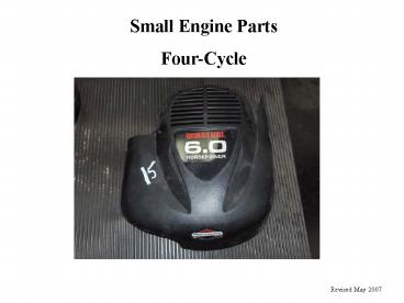
Small Engine Parts Four-Cycle
1. Crankcase
Revised May 2007
2
Engine Block
2. Cylinder Block
1. Crankcase
Crankcase Cover
3
Cylinder Block
1. Cylinder Bore
Head gasket goes here
3. Cooling Fins
2. Valves
4
Spark Plug
- Cooling Fins-Cooling fins keep heat away from the
cylinder block by increasing the surface area of
the cylinder block and contacting the already
existing cooler air for cooling efficiency.
5
Crankshaft
Throw-measurement from the center of the
crankshaft to the center of the crankpin journal.
Determines the stroke of an engine. Throw ½
stroke.
Crankshaft-converts the linear motion of the
piston into rotary motion.
Counterweights-balances the forces of the
reciprocating piston and reduces the load on
crankshaft bearing journals.
Crankgear-interlocks with the cam gear to turn
the crankshaft
6
Crankshaft
Crankpin Journal-attaches the connecting rod to
the crankshaft
Magneto Journal
- PTO Journal
Bearing Journal
7
Piston
Rings
Skirt
Piston Head
Piston Pin Bore
8
Piston Rings
1. Compression Ring-seals the combustion chamber
from any leakage during the combustion process.
2. Wiper Ring- used to further seal the
combustion chamber and to wipe the cylinder wall
clean of excess oil.
3. Oil Ring-Wipes excess oil from the cylinder
wall during piston movement. Openings in the
ring returns the excess oil to the engine block.
9
Ring Grooves
Ring Lands
10
Connecting Rod-transfers motion from the piston
to the crankshaft and functions as a lever arm
Piston Pin
Piston
Piston pin Bearing Surface
- Crankpin Journal Bearing Surface
Rod Cap
11
Valve Tappets
Valve Tappets-Rides on the camshaft and pushes
the bottom of the valve stem to open the valve
12
Cam Shaft- includes cam gear and cam lobes
driven by the crank gear
1. Cam Gear-portion of the camshaft that
interlocks with the crankgear.
2. Cam Lobes- egg-shaped protrusion on the
camshaft that moves a tappet to open a valve
controls the lift and duration of the opening and
closing of the valves
Timing Mark
13
Valve Retainer
Valve Spring
Valve Stem
- Valve Head
Intake Valve- allows the air-fuel mixture to flow
into the cylinder
Exhaust Valve- allows exhaust valves to flow out
of the cylinder
14
Flywheel
Flywheel Nut
15
Magneto
Spark Plug Wire
Armature
Magneto
16
Air Filter
17
Carburetor
Carburetor- provides the proper mixture of air
and fuel to the intake valve
18
Intake Manifold/Venturi
19
Muffler
Muffler Guard
20
Breather Assembly
Breather Cover
21
Shields
Cylinder Shield
22
Dipstick
23
Starter Housing
24
Gas Tank
25
Blower Housing Cover


