1st Order Inner Layer Layout - PowerPoint PPT Presentation
Title:
1st Order Inner Layer Layout
Description:
Heat load assumption for 800mm length=120W ... Castellated and non-castellated design. One layer design selected to quantify issues ... – PowerPoint PPT presentation
Number of Views:14
Avg rating:3.0/5.0
Title: 1st Order Inner Layer Layout
1
1st Order Inner Layer Layout
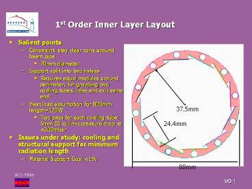
- Salient points
- Constraint stay clear zone around beam pipe
- 70mm diameter
- Support split into two halves
- Requires equal modules around perimeter for
grouping two cooling tubes, inlet and exit same
end - Heat load assumption for 800mm length120W
- Two pass for each cooling tube 5mm ID to limit
pressure drop to lt200mbar - Issues under study cooling and structural
support for minimum radiation length - Material Support Goal lt1
37.5mm
24.4mm
88mm
2
Preliminary Pixel Inner Layer Study
- Solid Models
- Examined various options for single and double
layer pixels - Initial objective was to combine both layers with
on support structure - Castellated and non-castellated design
- One layer design selected to quantify issues
- Cooling solution looks OK
- Proceeding to structural model
3
Pixel Thermal Solution-1st Order
- Description
- Isotropic carbon foam 50W/mK
- Specialized low density (0.14g/cc) foam enhanced
to high conductivity - Interface resistance from bonding chip to foam
equal to 0.8W/mK 4mil thickness - Pixel chip heating 0.6W/cm2
- Simulated tube wall temperature-22ºC
- Results
- Peak chip edge temperature-17.25 ºC
- Next slide illustrates chip temperature beneath
detector
4
Thermal Solution (Continued)
- Surface temperature of electronic chip, detector
removed for clarity
5
Structural Model of Inner Pixel Layer
- Model length 800mm, with supports at two end
- Will address gravity sag fully loaded with
modules and cooling tubes - Assess benefit, or need, of connecting two halves
to form circular structure - Examine prospect of using carbon foam to tie
tubes into a common structure as was as acting as
high conductivity media - Anticipate need for single layer composite to
enhance stiffness applied to outer and inner
foam surface - Limit material radiation length to 0.13 for both
surfaces


