Vibration Isolation for a Scanning Tunneling Microscope - PowerPoint PPT Presentation
1 / 1
Title:
Vibration Isolation for a Scanning Tunneling Microscope
Description:
Scanning Tunneling Microscope. The above photo is of an STM, mounted on the end of a probe, which will be ... A scanning tunneling microscope is an instrument ... – PowerPoint PPT presentation
Number of Views:57
Avg rating:3.0/5.0
Title: Vibration Isolation for a Scanning Tunneling Microscope
1
Vibration Isolation for a Scanning Tunneling
Microscope Tim McArdle, University of Illinois at
Urbana-Champaign
STM Basics
Vibration Isolation
- A scanning tunneling microscope is an instrument
capable of obtaining topographic and
spectroscopic images of conducting samples with
atomic resolutions. - Components
- A sharp conducting tip (ideally with a single
conducting atom at the end). - Piezoelectric actuators to control tip position.
- A conducting sample held close enough to permit
electron tunneling. - Voltage bias applied between tip and sample.
- Tunneling current depends on density of states
(DOS) of the sample, work functions of the tip
and sample, the voltage bias. - Strongest dependence is on the gap between tip
and sample exponential dependence leads to
atomic image resolution
- Normal ambient mechanical vibrations in the lab
are on the order of a few thousand angstroms
(1.010-7 m). - The most prevalent vibrations occur at 60 Hertz
and harmonics caused by machinery (vacuum pumps,
fans, etc.). - This noise can cause serious problems while
taking STM measurements. In order to achieve
atomic resolution, the tip to sample gap must be
controlled to within five hundredths of an
angstrom (5.010-12 m). - The lab is designed to minimize the severity of
vibrations coupling to the tip to sample gap. - Vacuum pumps are moved to the sub-basement, the
connecting hoses run through sandboxes. - The STM is inside the cryostat, supported by air
springs, and situated on solid ground.
The Air Spring System
First Stage (Air Springs)
- First stage four air springs support the
cryostat, STM, and control electronics. - Second stage four optical table legs support the
first stage plus additional mass added to improve
vibration isolation. - Model the system elements as a series of simple
harmonic oscillators. - Determine response of the gap width to external
driving signals. - Find the optimum isolation which can be achieved
within the physical constraints of the system.
Topographic Images (STM)
Second Stage (Optical Table Legs)
Sample Space
- Topographic image may be taken in two ways
- Constant Separation
- Hold bias voltage and tip to sample separation
constant. - Changes in current are measured and plotted
against position as the tip is scanned across the
sample. - This method is fast, but there is a risk that the
tip will crash into the sample. - 2) Constant Current
- Hold bias voltage and tunneling current constant.
- Variations in the height of the sample surface
force the tip to change position. - The change in separation is plotted versus
position over the sample. - This method is the standard method.
Sample Support Bearings
- Assume that ground vibrations may be approximated
as . - Insert this solution into Newtons Equations for
the isolation system - and .
- Calculate the transfer function describing the
response of the first stage mass to ground
vibrations and multiply by the transfer function
of the scope stage. - Optimize the vibration isolation is optimum when
? ? ?, and ? is reduced as much as
possible, but the actual operation is limited by
the amount of mass which can physically be added
to the spring system before the springs fail. - Plot the gap widths response, as is shown below
for a second stage mass of 300 kg. - Check the response of the gap width at a
frequency of 60 Hertz, is approximately 210-8
multiplied by the amplitude of the oscillation.
So for a signal with amplitude 1.010-7 m at 60
Hz, the response is on the order of 1.010-15 m,
well below the necessary threshold.
Spectroscopic Images (STS)
- Hold the tip to sample gap constant the
dominant effect on the current is the DOS of the
sample. - Sweep the bias voltage and measure the change in
current. - The change in current with respect to the change
in voltage is called the differential
conductance. - In the low temperature limit, the conductance is
proportional to the density of states. - Graph at right is the differential conductance
of a semiconductor near a defect.
Tip Holder Piezotube
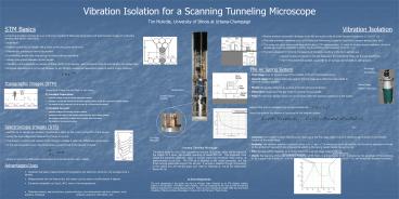
Scanning Tunneling Microscope The above photo is
of an STM, mounted on the end of a probe, which
will be placed at the bottom of a liquid 3He
cryostat operating at about 270 mK. The expanded
circle shows the piezotube assembly, which is
housed inside the cylindrical metal casing, at
approximately actual size. The STM tip is
attached to the center piezotube, and the three
outlying piezotubes support the sample. A sample
is inserted through the opening in the casing
into the sample space and rests on bearings on
top of the piezotubes, above the tip.
Scope Resonance
Spring Stage Resonances
Advantages/Uses
- Localized real-space measurements of
topographic and electronic structure, not
averaged over a sample. - Measurements are non-destructive, but system
can be used to modify sample if desired. - Extremely adaptable air, liquid, UHV room or
low temperatures. - Materials science, semiconductors,
superconductors, low-dimensional quantum systems,
nano systems, biological systems, quantum
information, etc.
Acknowledgments The work represented in this
poster was done at Michigan State University on
an STM vibration isolation system in the
laboratory of Professor Stuart Tessmer. And was
supported by MSU and the NSF through the Research
Experience for Undergraduates program. Follow up
work, including the poster itself, was done at
the University of Illinois at Urbana-Champaign in
conjunction with the Senior Thesis course.


