
Why Internet Engineering Course Objectives - PowerPoint PPT Presentation
1 / 323
Title:
Why Internet Engineering Course Objectives
Description:
Network byte order calls for the MSByte to be sent first. This is referred to as 'Big Endian' ... headers and data to network byte order before transmission ... – PowerPoint PPT presentation
Number of Views:175
Avg rating:3.0/5.0
Title: Why Internet Engineering Course Objectives
1
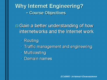
Why Internet Engineering? - Course Objectives
- Gain a better understanding of how internetworks
and the Internet work - Routing
- Traffic management and engineering
- Multicasting
- Domain names
2
Why Internet Fundamentals? - Course Objectives
(cont)
- Examine the effect of massive proliferation of IP
devices - SCADA
- Rockwell Automation
- Wireless Web PCS phone
- Intelligent Refrigerator
3
SCADA?
- Supervisory Control and Data Acquisition
- Use of TCP/IP networks for
- Utility monitoring
- Telemetry collection
- Factory control functions
- Active worldwide standards bodies
4
Why Internet Engineering? - Course Objectives
(cont)
- Learn how to make the variety of physical layer
technologies work together - Ethernet
- 802.11
- ATM
- Frame Relay
- Packet over SONET (POS)
- Packet over DWDM
5
Connectionless Architectures
- Advantages
- Redundancy/Survivability
- Recoverable
- Disadvantages
- Segmentation/Reassembly
- Intractable
6
Connection-oriented Arch.
- Advantages
- Controllable/Tractable
- Fast exchange post-setup
- Disadvantages
- Signalling
- Overhead
- Slower recovery
7
Proposed Solutions
- Multiprotocol Label Switching (MPLS)
- Multiprotocol ? (wavelength) Switching
- Differentiated Services (Diffserv)
8
Layering
- Client/Server Model
- Routers/Gateways (Multihomed)
9
(No Transcript)
10
TCP/IP Overview
- Addressing
- The Domain Name System
- Demultiplexing
- Implementations (BSD4.4)
11
IP issues
- How is a message delivered across multiple link
technologies? - - Addressing
- - Routing
12
IP v. 4 Addresses
- 32-bit identifier that is globally unique to the
network - Represented in text using the dotted decimal
format - Four decimal numbers separated by periods
- 00000001 00000010 00000011 00000100 is 1.2.3.4 in
dotted decimal format
13
IP v. 4 Address Structure
n bits
m bits
32 n - m bits
netid
subnetid
hostid
- Route to
- - Netid
- Subnetid
- Host
14
IP v. 4 address prefixes
- A specific netid or netid/subnetid prefix is
represented with the format - IPv4 address with zeroes/id length
- NPS netid is 131.120.0.0/16
- NPS Spanagel Hall netid/subnetid is
131.120.96.0/20 - Whether an id is a netid or subnetid depends on
the context (e.g. ISP or organization)
15
Reserved Special Use IP Addresses
Address Block Present Use
Reference ------------------------------------
---------------------------------------- 0.0.0.0/8
"This" Network
RFC1700, page 4 10.0.0.0/8 Private-Use
Networks RFC1918 14.0.0.0/8
Public-Data Networks RFC1700,
page 181 39.0.0.0/8 Reserved but subject
to allocation RFC1797 127.0.0.0/8
Loopback RFC1700,
page 5 128.0.0.0/16 Reserved but subject
to allocation -- 169.254.0.0/16 Link Local
-- 172.16.0.0/12
Private-Use Networks
RFC1918 191.255.0.0/16 Reserved but subject
to allocation -- 192.0.0.0/24 Reserved but
subject to allocation -- 192.0.2.0/24
Test-Net 192.88.99.0/24 6to4 Relay Anycast
RFC3068 192.168.0.0/16
Private-Use Networks
RFC1918 198.18.0.0/15 Network Inet Device
Benchmark Testing RFC2544 223.255.255.0/24
Reserved but subject to allocation
-- 224.0.0.0/4 Multicast
RFC3171 240.0.0.0/4 Anycast
RFC1700, page 4
16
Use of IP Address Space
Network Wizards (nw.com) Dec 2001
17
Summary of Old Class A, B, C Networks (pre-1994)
Class
Leading Bit Pattern
Decimal Range of First Byte
Number of Networks
Number of Nodes / Network
A
0
1-127
127
16,777,214
B
10
128-191
16,384
65,534
C
110
192-223
2,097,152
254
e.g., Class B Network
7 6 5 4 3 2 1 0
7 6 5 4 3 2 1 0
13 12 11 10 9 8
15 14 13 12 11 10 9 8
21416,384 216 65,536
18
Three Levels of Identity
- Domain Name pcrfb2.ece.nps.navy.mil
- IP Address 131.120.103.107
- Physical Address 00107A901613
- Domain Name -gt IP Address Domain Name Service
Hosts File - IP Address -gt Physical Address Arp Table /
Broadcast
19
IP v. 6 Addresses
- Standardized in 1995, uses a 128-bit addresses
- 4 billion x 4 billion x 4 billion x 4 billion
- Represented in text by 16-bit hexadecimal values
separated by colons - FEDCBA9876543210FEDCBA9876543210
- 10800008800200C417A
20
IP v. 6 Addresses (cont)
- Compressed format uses to represent long
strings of zeroes - FF01000000101 becomes FF01101
- IPv4 addresses migrate to IPv6 by adding leading
zeroes - Keep dotted decimal representation
- 131.120.96.1 is 131.120.96.1 in IPv6
- IPv4 default addresses take up 1/296 of IPv6
address space
21
IP v. 6 Address Structure
n bits
m bits
128 n - m bits
Global routing prefix
subnetid
Interface id
- Prefix representation is the same as IPv4
- A Global routing prefix of length 60 bits and
value 12AB00CD300000 could be represented
by - 12AB00000000CD300000000000000000/60
- 12ABCD300000/60
- 12AB00CD30/60
22
Special IPv6 Addresses
- The loopback address 1
- Link-local addresses
- Begin with 1111 1110 10
- Intended to be transmitted only on attached
segment - Never forwarded by router
- Site-local addresses
- Begin with 1111 1110 11
- Intended to be transmitted only within
organization
23
IPv6 Address Space Allocation
Allocation Prefix
Fraction of
(binary) Address Space
----------------------------------- --------
------------- Reserved (IPv4 migration
others) 0000 0000 1/256 Unassigned
0000 0001 1/256
Reserved for NSAP Allocation 0000 001
1/128 RFC1888 Unassigned
0000 01 1/64 Unassigned
0000 1 1/32
Unassigned 0001
1/16 Global Unicast
001 1/8 RFC2374 Unassigned
010 1/8
Unassigned 011
1/8 Reserved for Geographic-based Unicast
100 1/8 Unassigned
101 1/8 Unassigned
110 1/8
Unassigned 1110
1/16 Unassigned
1111 0 1/32 Unassigned
1111 10 1/64 Unassigned
1111 110 1/128
Unassigned 1111 1110 0
1/512 Link-Local Unicast Addresses
1111 1110 10 1/1024 Site-Local Unicast
Addresses 1111 1110 11 1/1024
Multicast Addresses 1111 1111
1/256
24
Why IP v. 6?
- Running out of IPv4 addresses
- More people in the world than possible IPv4
addresses - 70 of IPv4 addresses held by U.S. ISPs
- Example Level3 alone has rights to more IPv4
addresses than all ISPs in Asia - OSD CIO mandates DoD transition by FY2008
(www.moonv6.org) - Large vendor support
25
Why not IPv6?
26
Why not IPv6? (cont)
- Not really running out of IPv4 addresses
- NAT-PT slowing rate of demand
- Most organizations use less than 20 of
allocation - IPv6 has large overhead
- No economic motivation for organizations to
switch - Transition will fractionalize Internet require
protocol translators - Support in U.S. is poor (except for vendors)
27
(No Transcript)
28
(No Transcript)
29
Border Gateway Routing Tables
30
Demultiplexing
31
Demultiplexing
- Allows multiple applications to use one network
point of entry - How do we know what port to use? gt
well-known ports
32
Well-Known Ports
- On UNIX look in /etc/services
- Ports 1 - 1023 require superuser/Administrator
access to assign (For authentication purposes) - Comprehensive list via www.iana.org
http//www.isi.edu/in-notes/iana/assignments/port-
numbers - RFC 1700 provides Internet standard
33
Request For Comments (RFC)
- Official standards of the Internet Community
- Usually the best place to start
- Published by Internet Engineering Task Force
(IETF) (www.ietf.org/rfc) - Obtain via e-mail to rfc-info_at_ISI.EDU
34
RFCs (cont)
- Also available in ASCII form from ISI
(http//info.internet.isi.edu/1/in-notes) - Searchable versions in HTML http//www.pmg.lcs.mit
.edu/rfc.html
35
Important RFCs
- Assigned s RFC 1700
- Official Protocol Standards 2200
- Host Requirements 1122, 2181
- Router Requirements 1812
36
(No Transcript)
37
Endian
- Network byte order calls for the MSByte to be
sent first. This is referred to as Big Endian - RISC processors commonly used by Macs and UNIX
are big endian - Intel processors use little endian and must
convert headers and data to network byte order
before transmission
38
IP Header Fields
- Version is either 4 (0100) or 6 (0110)
- Header Length is of 32-bit words in header
including any options - 4 bits gt Max header size is 60 bytes
- Normal value is 5 (no options)
- Type of Service is not traditionally used
(usually zero). Diffserv is exception.
39
IP Header Fields (cont)
- Total Length is the total length of the IP packet
in bytes - Compute length of data using hdr length
- 16 bits gt Max size of IP datagram is 65,535
bytes - Most link layers will fragment
- Necessary with padded link layer frames
40
IP Header Fields (cont)
- The Identification field generally increments one
for each datagram sent - Used to reassemble fragmented IP packets
- Fragmentation options are provided by the three
flag bits - First bit is reserved for future use
- Second bit on (1) indicates Dont Fragment
- Third bit off (0) means last fragment
41
IP Fragmentation Example
Original Datagram
Fragment 1
Fragment 2
More Bit 1 when another fragment follows Frag
Offset Offset in 8 byte units
Data Length
472
240
232
0
0
30
Frag. Offset
0
1
0
More Bit
42
IP Header Fields (cont)
- The TTL field limits the lifetime of the datagram
by restricting the number of routers it can pass
through - The protocol field is used for demultiplexing
- The header checksum is a 16-bit ones complement
of the sum of each 16 bit segment in the header
43
IP Header Fields (cont)
- Source and Destination addresses
- Options
- security and handling Specifically used with DoD
applications to pass classification level of data
(see RFC 1108) - record route
- source routing
44
IP Routing
- From the hosts perspective
- If the destination is directly connected (on the
same LAN), send the datagram directly to the
destination - Otherwise send the datagram to the router
45
IP Routing (cont)
- Routers use a routing table to determine where
next to send - Routing table consists of
- Destination host or network address
- IP address of next-hop router
- Flags that specify what the next-hop router is
(e.g. - a host, a router) and if its up - The interface to transmit out
46
IP Routing (cont)
- Routing table lookup is performed for each packet
generated - Implies router performance is due in large part
to efficiency of lookup algorithm - No router knows the complete route to the
destination
47
IP Routing Algorithm
- 1. Look for an exact match of incoming IP address
within routing table - 2. Search routing table for a matching network ID
- 3. Search the routing table for a default entry
- 4. Return a host/network unreachable ICMP
packet.
48
INTERNET
192.1.3.0 Network
192.1.3.1
192.1.0.20
192.1.2.2
192.1.2.1
ie1
Dest Gateway Flags Interface 127.0.0.1 127.0.0.1 H
lo0 192.1.1.2 192.1.1.1 ar0 192.1.3.0 192.1.2.1
G ie1 192.1.2.0 192.1.2.101 ie1 192.1.4.0 192.1.4
.1 ie0 default 192.1.2.2 G ie1
192.1.2.101
192.1.1.1
192.1.1.2
ar0
PPP
192.1.4.1
ie0
192.1.4.2
192.1.4.3
49
Alternative Routing Table Representations
Windows NT (netstat -nr or route print)
Network Address Netmask Gateway
Address Interface 127.0.0.0 255.0.0.0 127.0.0.1
127.0.0.1 192.1.1.2 255.255.255.255 192.1.1.1 1
92.1.1.1 192.1.3.0 255.255.255.0 192.1.2.1 192.1
.2.101 192.1.2.0 255.255.255.0 192.1.2.101 192.1
.2.101 192.1.4.0 255.255.255.0 192.1.4.1 192.1.4
.1 0.0.0.0 0.0.0.0 192.1.2.2 192.1.2.101
Cisco IOS (show ip route)
Gateway of last resort is 192.1.2.2 to network
0.0.0.0 192.1.1.2/32 is directly connected,
Serial0 192.1.3.0/24 via 192.1.2.1,
Ethernet1 192.1.2.0/24 is directly connected,
Ethernet1 192.1.4.0/24 is directly connected,
Ethernet0 0.0.0.0/0 via 192.1.2.2, Ethernet1
50
Subnet Addressing
- Divides the host ID of an IP address into a
subnet ID and a host ID - Not restricted to 8-bit boundary although a
common practice - EC was 131.120.20.0
- Now in range of 131.120.96.1 - 131.120.111.255
51
Subnet Masks
- Allows a host to know whether the destination is
- on its own subnet,
- on a different subnet in its own AS
- on a different network
- Subnet mask identifies where the boundary is
between subnet ID and host ID
52
Managing Interfaces
- UNIX ifconfig -a
- NT ipconfig /all
- Win95 winipcfg
- Allows interface options to be set/identified
(including media type, encapsulation options,
status, etc.)
53
Interface Statistics
- UNIX netstat -in (basic, cmd line)
- NT Network Monitor (Graphical)
- Allows user to view activity on a per interface
basis
54
Address Resolution Protocol
- Provides a dynamic mapping between an IP address
and the corresponding hardware address - Normally an automatic process
- Flexible packet format allows use over multiple
media
55
Operation - 1 ARP request, 2 ARP reply,
3 RARP request, 4 RARP reply
56
(No Transcript)
57
ARP Operation
- On Ethernet, host broadcasts a request to all
stations. Station with corresponding IP address
responds. - On ATM, designated ARP server responds to all
requests - ARP request usually precedes most connection
requests unless mapping is cached
58
ARP Cache
- ARP entries are cached locally for 3 to 20
minutes depending on OS. - To view current cache arp -a (valid on UNIX, NT
and Win95)
59
Gratuitous ARP
- Most systems on bootstrap transmit an ARP request
for their own IP address - Lets host know if another host is already
configured with that IP address - Forces other hosts (or ARP server) to update
their cache if either hardware or IP address has
changed recently
60
Reverse ARP
- Used by diskless systems that need to acquire
their OS from a remote host - Requires unicast connection with a RARP server
- Packet is same format as ARP
61
Internet Control Message Protocol
- Reports errors and messages related to IP
datagrams - Usually acted upon by either the IP layer or
higher layer protocol - Encapsulated within IP datagrams
62
(No Transcript)
63
ICMP Restrictions
- An ICMP error message is never generated in
response to - An ICMP error message.
- Datagrams addressed to broad-/multicast
- Datagrams sent as link-layer broadcasts
- A fragment other than the first
- Datagrams whose source does not specify a single
host.
64
ICMP Error messages
- Must include the IP header ( options) of the
datagram generating the error with the first 8
bytes that followed this header. - Consequently, TCP and UDP headers specify their
source and destination ports in the first 8
bytes. - Assists in identifying the error.
65
ICMP Message Processing
- Each ICMP message is handled differently
- All user processes eventually receive a copy of
all ICMP messages - Occasionally, the kernel may handle an ICMP
message first
66
(No Transcript)
67
ICMP Message Processing (cont)
- For ICMP queries
- The sending application stores the value in the
identifier field for future identification - The sequence number field allows the client to
match replies with requests
68
Ping
- Small program that uses ICMP echo request/echo
reply messages to test whether a destination is
reachable - Generally the starting point in troubleshooting
- Often tied directly to the kernel OS
69
(SunOS requires ping -s)
70
Timer Resolution
- Hardware clock generates an interrupt at a
periodic frequency. - For i960 and 80386 processors, interrupts occur
every 10ms. - Missed interrupts will cause the system to lose
time - 0.01 tolerance implies error of 8.64 seconds per
day
71
Timer Resolution (cont)
- To keep better time requires
- a better or separate oscillator
- an external time source (e.g. - GPS)
- access via the Internet to more precise clocks
(e.g. - NTP) - New UNIX/P3/P4 systems include a high resolution
timer provides microsecond resolution.
72
Ping IP Record Route
- Forms record of actual route travelled by query
and reply - UNIX ping -Rsv lthostnamegt
- NT/95 ping -r records lthostnamegt
- Due to restriction on size of IP header, can only
record 9 visited IP addresses
73
C\WINDOWSgtping -r 9 alioth.cc.nps.navy.mil Pingi
ng alioth.cc.nps.navy.mil 131.120.54.2 with 32
bytes of data Reply from 131.120.54.2 bytes32
time4ms TTL251 Route 131.120.0.2 -gt
131.120.34.2 -gt 131.120.253.57 -gt
131.120.54.1 -gt 131.120.54.2
-gt 131.120.253.222 -gt
131.120.34.1 -gt 131.120.0.1 -gt
131.120.20.1
74
C\WINDOWSgtping -r 7 alioth.cc.nps.navy.mil Pingi
ng alioth.cc.nps.navy.mil 131.120.54.2 with 32
bytes of data Reply from 131.120.54.2 bytes32
time6ms TTL251 Route 131.120.0.2 -gt
131.120.34.2 -gt 131.120.253.57 -gt
131.120.54.1 -gt 131.120.54.2
-gt 131.120.253.222 -gt
131.120.34.1 C\WINDOWSgtping -r 10
alioth.cc.nps.navy.mil Bad value for option -r.
75
C\WINDOWSgttracert alioth.cc.nps.navy.mil Tracing
route to alioth.cc.nps.navy.mil
131.120.54.2 over a maximum of 30 hops 1
1 ms 1 ms 1 ms 131.120.20.1 2 1
ms 1 ms 1 ms 131.120.0.1 3 1 ms
1 ms 2 ms 131.120.34.1 4 2 ms 1
ms 1 ms zeta.nps.navy.mil 131.120.253.222
5 3 ms 2 ms 2 ms alioth.cc.nps.navy.
mil 131.120.54.2 Trace complete. lt103 alioth
/joshua_u3/mceachengt /usr/etc/traceroute
pcjcm3.ece.nps.navy.mil traceroute to
pcjcm3.ece.nps.navy.mil (131.120.20.204), 30 hops
max, 40 byte packets 1 131.120.54.1
(131.120.54.1) 1 ms 1 ms 2 ms 2
star.nps.navy.mil (131.120.253.57) 2 ms 2 ms 2
ms 3 131.120.34.2 (131.120.34.2) 2 ms
(ttl62!) 2 ms (ttl62!) 2 ms (ttl62!) 4
131.120.0.2 (131.120.0.2) 2 ms (ttl61!) 2 ms
(ttl61!) 2 ms (ttl61!) 5 pcjcm3.ece.nps.navy.
mil (131.120.20.204) 2 ms (ttl28!) 2 ms
(ttl28!)
76
C\WINDOWSgtping -r 9 maewestbr-aip.att-disc.net P
inging maewestbr-aip.att-disc.net
135.206.243.10 with 32 bytes of data Request
timed out. Request timed out. Request timed
out. Request timed out.
77
C\WINDOWSgttracert www.mtu.edu.mn Tracing route
to www.mtu.edu.mn 202.131.1.131 over a maximum
of 30 hops 1 1 ms 1 ms lt10 ms
131.120.20.1 2 1 ms 1 ms 1 ms
131.120.0.1 3 1 ms 1 ms 1 ms
131.120.34.1 4 2 ms 2 ms
131.120.254.20 5 4 ms 2 ms 3 ms
epsilon.nps.navy.mil 131.120.252.101 6 3
ms 3 ms 4 ms 131.120.250.2 7 24 ms
22 ms 23 ms maewestbr-aip.att-disc.net
135.206.243.10 8 25 ms 23 ms 22 ms
gip-mae-w-fddi.gip.net 198.32.136.94 9 29
ms 26 ms 26 ms gip-stock-1-hssi4-0.gip.net
204.59.128.33 10 964 ms 952 ms 953 ms
204.59.128.14 11 1106 ms 1043 ms 888 ms
202.167.59.10 12 1028 ms 1053 ms 748 ms
202.131.0.26 13 98 ms 96 ms 95 ms
gip-penn-1-fddi5-1-0.gip.net 204.59.136.193 14
91 ms 91 ms 90 ms gip-stock-2-hssi0-1-0.
gip.net 204.59.136.18 15 92 ms 93 ms
92 ms gip-stock-1-fddi11-0.gip.net
204.59.128.225 16 1035 ms 1037 ms 1025 ms
204.59.128.14 17 889 ms 1163 ms
202.167.59.10 18 1094 ms 845 ms 1111 ms
202.131.0.26 19 1077 ms 951 ms
192.168.0.18 20 1133 ms 1126 ms
192.168.0.1 21 1201 ms 1197 ms
202.131.1.1 22 1256 ms 1220 ms 1222 ms
www.mtu.edu.mn 202.131.1.131 Trace complete.
78
C\WINDOWSgttracert wgc.chem.pu.ru Tracing route
to wgc.chem.pu.ru 195.19.244.194 over a maximum
of 30 hops 1 1 ms 1 ms 1 ms
131.120.20.1 2 1 ms lt10 ms 1 ms
131.120.0.1 3 2 ms 1 ms 2 ms
131.120.34.1 4 2 ms 9 ms
131.120.254.20 5 15 ms 5 ms 3 ms
epsilon.nps.navy.mil 131.120.252.101 6 177
ms 30 ms 3 ms 131.120.250.2 7 271 ms
92 ms 254 ms pennsbr-aip.att-disc.net
135.206.247.5 8 90 ms 90 ms 90 ms
sl-nap1-pen-F0/0/0.sprintlink.net 192.157.69.9
9 95 ms 135 ms 111 ms sl-bb10-pen-5-3.spr
intlink.net 144.232.5.61 10 114 ms 88 ms
127 ms sl-bb12-pen-9-0.sprintlink.net
144.232.5.153 11 95 ms 96 ms 103 ms
sl-gw16-pen-0-0-0.sprintlink.net 144.232.5.94
12 182 ms 191 ms 114 ms sl-teleglob-6-0-0-T
3.sprintlink.net 144.228.181.10 13 117 ms
149 ms 125 ms gin-nyy-core1.Teleglobe.net
207.45.223.166 14 109 ms 126 ms 124 ms
gin-ppt-bb1.Teleglobe.net 207.45.199.234 15
241 ms 232 ms RUNNet-gw.Teleglobe.net
207.45.206.246 16 303 ms 249 ms 262 ms
StPetersburg-gw-ATM0-1.RUN.Net 193.232.80.102
17 263 ms 252 ms 242 ms spb-ix.runnet.ru
194.85.36.34 18 257 ms 245 ms 254 ms
StPetersburgSU-2048K.RUN.Net 194.85.165.174 19
1507 ms PTCgate-4.spbu.ru
195.19.226.27 20 1151 ms 1535 ms 555 ms
195.19.244.2 21 1798 ms 311 ms 355 ms
wgc.chem.pu.ru 195.19.244.194 Trace complete.
79
Traceroute
- Send UDP datagrams starting with TTL1 and
increase the TTL by 1 with each iteration. - An ICMP time exceeded is returned by each
router in turn - An ICMP port unreachable is generated by the
destination
80
Traceroute and Source Routing
- Traceroute has options that force packets to
travel via specified routers - Strict source routing (-G) - datagram must
travel through each node only as specified in the
list (only in UNIX) - Loose source routing (-g/-j) - datagram must
visit specified nodes (but may be forwarded by
others)
81
More IP Routing
- How is the routing table determined?
- Through static entry using the route add
command (UNIX, NT) - Processing of an ICMP redirect message
- Dynamically, using a background process (or
daemon) to periodically exchange routing
information with other routers
82
Static Routes
- Advantages
- Consume minimum CPU resources and no link
bandwidth - More efficient on single-point, low bandwidth
links - Disadvantages
- Failure is not circumvented automatically
- Maintenance does not scale well
83
ICMP Redirect
- Allows a host with minimal routing knowledge
build a better routing table - Host can start with only a default route
- Hosts learn more as they receive redirects
- Keeps intelligence in routers
84
ICMP Redirect (cont)
85
ICMP Redirect Generation
- Outgoing interface Incoming interface
- Route used by outgoing datagram must not have
been from ICMP redirect and must not be the
default route - Datagram must not be source routed
- OS kernel must be configured to send redirects
86
Host Redirect Processing
- Before modifying the routing table
- New router must be directly connected
- Redirect must be from current entry for that
destination - Redirect cannot tell the host to use itself
- Route thats being modified must be an indirect
route
87
General ICMP Redirect Rules
- Redirects are generated by routers, not hosts
- Redirects are used by hosts not routers (because
routing daemons update router tables)
88
Routing Protocol Selection
- Path determination overhead
- Router CPU time
- Router memory
- Link Bandwidth
- Protocol support
- Support for VLSM
- Summarization
- Convergence Time
89
Summarization
Routing Table Net Mask
GW 131.120.2.0 255.255.254.0 131.120.0.7
Network ID 131.120.3.0 Subnet Mask
255.255.255.0
131.120.0.1
131.120.0.7
Network ID 131.120.2.0 Subnet Mask
255.255.255.0
90
Routing daemons
- UNIX uses one of two daemons, routed (strictly
for RIP) or gated (most open protocols) - routed comes with most UNIX distributions
- NT views the routing daemon as a Service that
may be added in the Network dialog box
91
A distinction...
- A routing mechanism is used to search the
routing table and determine which interface to
transmit on (usually done by IP) - A routing policy is a set of rules for
determining which routes go into the routing
table (performed by the routing daemon)
92
Routing Information Protocol
- Widely used Interior Routing Protocol
- Being replaced by Open Shortest Path First (OSPF)
- Supported by both routed and gated
- Encapsulated in a UDP packet with both ports
being 520 - Uses distance vector (Bellman-Ford) routing
algorithm
93
Command 1 request, 2 reply, 5 poll, 6
poll-entry Address family 2 for IP
94
RIP Procedure
- On initialization, sends a request on each
interface for neighbors routing tables - Neighbors forward entire routing table for
initialization request, otherwise, each route is
examined and assigned a metric
95
RIP Procedure (cont)
- Originating router receives responses from all
neighbors and updates routing table based on
least cost metric - Routing table updates are sent every 30 seconds
- If a metric changes, that entry is broadcast to
neighbors - No update after 3 minutes gt metric 16 and
route is marked for deletion
96
Route Metrics
- Metric of 16 is considered unreachable
- Metrics are hop counts
- Hop counts can be biased by administrator to
facilitate policy - Adjacent networks across a router have a default
metric of 1
97
RIP Problems
- Takes a long time to stabilize after failure
resulting in routing loops - No knowledge of subnet addressing
- Maximum metric of 15 limits the size of networks
using RIP - Use of hop count as routing metric omits more
significant parameters
98
RIP-2 (1993)
- Extensions to original RIP attempt to address
RIPs problems - Authentication with a cleartext password
- Passes subnet mask
- Supports VLSM
- Next-hop IP address allows interaction with OSPF
and EGPs.
99
(No Transcript)
100
Open Shortest Path First (OSPF)
- Link-state protocol - Djikstras algorithm
- Developed to address the needs of large, scalable
networks that RIP could not. - A single link-state database is maintained by
all routers in an area - Each router is responsible for maintaining and
disseminating information about its interfaces
in the link-state database
101
OSPF (cont)
- A router creates link-state advertisements
(LSA) that are eventually forwarded to all other
routers using flooding - Remaining routers enter this information into
their copy of the link-state database - Each router then computes its own routing table
from the values in the link-state database
102
Typical Flooding Message from
A _______________________ From A, to B, link 1
distance 1 From A, to D, link 3
distance 1 (distance is the metric, link is a
label for the link)
103
Why is OSPF Better?
- Fast, loopless convergence
- Given N nodes and M links, Bellman-Ford converges
in O(NM), Djikstra converges in O(MlogM) - RIP uses distributed computation - number of
steps required is proportional to the number of
nodes. Can take minutes. - OSPF floods first then does a local computation
104
Why is OSPF Better? (cont)
- Support multiple metrics simultaneously
(corresponding to IP TOS) - Maximum Throughput
- Minimize Delay
- Minimize Monetary Cost
- Maximize Reliability
- Can calculate a separate set of routes for each
105
Why is OSPF Better? (cont)
- Supports multiple paths to a destination
- Availability of link-state database allows
determination of alternative routes - Can distribute traffic between routes to minimize
congestion gt load balancing - Support for VLSM (not in RIP v.1)
- Network reachability RIP limited to 15 hops.
OSPF virtually no limitations
106
Why is OSPF Better? (cont)
- Use of bandwidth RIP broadcasts entire routing
table every 30 secs. OSPF multicasts updates only
if change or 30 minutes - Support representation of external routes
107
Why isnt OSPF better?
- Extremely complex. (RFC 2178 at 211 pages is one
of the longest) - Requires considerable design foresight to take
advantage of features - Proper summarization of address space
- Identification of areas
- Metric assignment
108
OSPF Design
- Protocol runs directly on top of IP (protocol
type 89) - Composed of three subprotocols hello, exchange,
and flooding - Additionally, five message types Router Links,
Network Links, Summary Links, Summary to a
border, and External Links
109
OSPF Operation
- 1. Establish router adjacencies.
- 2. Elect a designated router.
- 3. Discover routes.
- 4. Select appropriate routes to use.
- 5. Maintain routing information.
110
Router Adjacencies
- OSPF is dependent on link status
- A router must recognize its neighbors
- Send a hello message to multicast address
224.0.0.5 - Maintain adjacencies database
- Hello messages continue to be sent every 10
seconds
111
Designated Routers (DR)
- In situations where multiple routers exist on one
segment, a DR and a backup DR (BDR) are elected
112
Discovering Routes
- When a new adjacency (router) is identified, the
DR is responsible for initializing the new router - Exchange messages are used to provide a summary
of the DRs link-state database
113
Maintaining Routes
- All LSAs are sent to the DR (and BDR) at
224.0.0.6 - DR repackages LSA in an LSU and forwards it to
all other routers at 224.0.0.5
114
(No Transcript)
115
Large OSPF Networks
- Issues associated with very large networks
include - Frequent cost calculations routers spend many
more CPU cycles recalculating routing table - Large routing table
- Large link-state database need entry for every
link in network
116
Large OSPF Networks (cont)
- Previous issues can cause
- Routers to run out of memory
- Routers to receive more LSAs than data to route
- Route recalculation takes up more CPU time than
routing, causing buffer overflows and dropped
packets - OSPFs answer Multiple Areas
117
OSPF Areas
- OSPF provides the capability to separate a large
Autonomous System (AS) into several areas - Referred to as hierarchical routing
- LSUs are restricted to a specific area
- Use summarization to perform inter-area routing
118
Route Flapping
- Often a defective interface will turn on and off
in rapid succession - This will cause the router to generate an LSA in
each case - The LSA causes every router in the area to
recalculate its link-state DB - This is called route flapping
- Multiple areas reduce the propagation of route
flaps
119
Area Design
- All OSPF routed networks consist of a backbone
area called Area 0 - All other areas must connect with area 0
- Possible to attach an area to area 0 through
another OSPF area using a virtual link. Not
recommended. - Limit each area to less than 100 routers
- No more than 28 areas in the network
120
Components of Multiple Areas
- Area Types
- Router Types
- LSA Types (discussed in OSPF design)
121
OSPF Router types
- Internal router All interfaces are in the same
area. Internal routers in the same area have
identical link-states DBs. - Area Border Router (ABR) Have interfaces
attached to multiple areas. Maintain separate
link-state DBs for each attached area. Summarize
routes.
122
OSPF Router types (cont)
- Backbone router Has at least one interface
connected to the backbone area - AS Boundary router Have at least one interface
into another AS. Can import non-OSPF information
to the OSPF network
123
Area Types
- Standard Area An area that can accept LSUs and
route summaries - Backbone Area The central entity to which all
other areas connect. Always labeled 0. - Stub Area Does not accept information external
to the AS. - Totally Stubby Area Does not accept information
external to the area. Relies on default route.
124
(No Transcript)
125
Exterior Routing Protocols
- Exterior Gateway Protocol (EGP)
- First interdomain routing protocol
- Viewed the Internet as a tree topology with a
single backbone (NSFNet) - Autonomous Systems (AS) connected only as parents
and children and not as peers
126
(No Transcript)
127
Border Gateway Protocol (BGP)
- Assumes the Internet is an arbitrarily
connected interconnected set of ASs - Currently in its fourth version (BGP-4)
- Implemented within gated
- Facilitates multiple-backbone service provider
networks owned by private companies - Allows policy to determine paths
128
(No Transcript)
129
More about ASs
- Local traffic is defined as traffic that
originates at or terminates on nodes within an AS - Transit traffic is traffic that passes through
an AS
130
AS Types
- stub AS - has a single connection to one other
AS only carries local traffic - multihomed AS - has connections to more than
one other AS but refuses to carry transit traffic - transit AS - has connections to more than one
other AS and is designed to carry both transit
and local traffic
131
BGP Operations
- Each AS has at least one BGP Speaker
- In addition, the AS has one or more border
gateways, which need not be the same as speakers - Border gateways act as interfaces to other ASs
132
BGP Operations (cont)
- Primary goal find any path to the intended
destination that is loop free - BGP is more concerned about reachability than
optimality - BGP speaker advertises reachability information
for all networks within its AS - In the case of transit ASs, speaker also
advertises networks that can be reached through
the AS
133
(No Transcript)
134
BGP Operations (cont)
- Establishes TCP connection (Port 179) for
information exchange - Initially, two systems exchange entire BGP
routing tables - Incremental updates are sent as routing table
changes (or unless connection is broken)
135
BGP Operations (cont)
- Detects failure of a link by sending a
keepalive message (different than TCP
keepalive) - Messages sent every 30 seconds.
- If link goes down, a negative advertisement known
as a withdrawn route is sent
136
BGP Operations (cont)
- BGP does not belong to either of the two main
classes of routing protocols - BGP advertises complete paths as an enumerated
list of ASs to reach a particular network - Necessary to enable policy decisions of certain
ASs - Also allows detection of routing loops
137
Acceptable Use Policy (AUP)
- Originally dictated by NSF advertised all
routes only to ASs devoted to science (limits
what traffic could transit) - Led to the development of commercial providers
allowing transit - In turn, led to the idea of peering between
service providers
138
Policies affect
- The choices of paths you advertise to your
neighbors - The choice of path you take to the destination
139
(No Transcript)
140
ATT Advertises Aussie Telecom via Iraqi Telecom
NPS
IRAQI TELECOM
ATT
AUSSIE TELECOM
PacBell Advertises Aussie Telecom via British
Telecom
BRITISH TELECOM
PACBELL
Which path should our traffic take?
141
When to use BGP?
- Connect to multiple ISPs
- Any time your policy requirements differ from the
policy of your ISP - If you want to AS to be advertised to the world
142
Why not use BGP?
- Protocol and management is complex
- Static or default route might suffice for stub
143
BGP Resources
- AS numbers are assigned by either the American
Registry for Internet Numbers (ARIN,
www.arin.net, Americas, Carib, Africa), RIPE-NCC
(Europe), or AP-NIC (Asia). - http//www.iana.org/numbers.html
- ftp//rs.arin.net/netinfo/asn.txt (Current ASs)
144
Border Gateway Routing Tables
145
Just-in-time Fixes
- Exhaustion of Class B addresses (92) gt
establishment of Class C addresses - Downside Increased size of routing tables gt
development of BGP-4/CIDR - Next hurdle exhaustion of IP addresses
146
Classless Interdomain Routing
- Class C address (256 hosts) is too narrow for
most organizations - Only 16,384 class B addresses available (50
allocated by 92) - Solution Offer organizations multiple contiguous
class C addresses
147
Use of IP Address Space
148
CIDR (cont)
- Consider multiple contiguous class C addresses as
one network - BGP only advertises the one network address
versus multiple addresses - Must also pass a 32-bit mask to indicate the
network ID - The best match is always the one with the longest
number of 1s
149
CIDR Example
- Suppose a AS 20 owns to the rights to 4 class C
addresses - The third byte of each corresponds to
- Hence applying a mask of 11111100 (252) masks the
variable bits and maintains the significant bits.
197.8.0.0 197.8.1.0 197.8.2.0
197.8.3.0
00000000 00000001 00000010 00000011
150
CIDR Example
- Applying the mask to any of the four class C
addresses yields 197.8.0.0 - Thus AS 20 can efficiently advertise the
supernet 197.8.0.0 with a mask length of 22
ones (corresponding to 252 in the third byte).
151
CIDR Example (cont)
- Suppose AS 20 is a service provider and leases
the address space 197.8.2.0 to AS 23 and the
address space 197.8.3.0 to AS 24. - AS 20 can still advertise paths to AS 23 and AS
24 with the aggregate NetID 197.8.0.0 and a mask
length of 22
152
CIDR Example (cont)
- Further, suppose AS 24 also peers with a second
service provider, AS 50. - AS 50 will advertise reachability to AS 24 of
NetID 197.8.3.0 and mask 24. - An AS upstream of both AS 20 and AS 50 will
choose the route through AS 50, barring any AUP,
because of the longer mask.
153
AS 10 10.0.0.0
AS23 197.8.2.0
AS 20 197.8.0.0 197.8.1.0
AS24 197.8.3.0
AS 50 150.8.0.0
AS 600 130.8.0.0
Longest match advertisement
154
Network Convergence
- Voice traffic is growing linearly
- Data traffic is growing exponentially
- In 1999, data traffic on carrier networks
exceeded voice traffic - Consequently, everyone is trying to get into the
data business (e.g. Cable modems)
155
Network Convergence (cont)
- In the past, data was fitted on to voice networks
- Today, large data requirement mandates networks
optimized for data (e.g. - packet switched) - In the future, voice will be fitted to data
networks - Issue Guaranteeing QOS
156
QoS in Packet Networks
- ATM
- Integrated Services w/ RSVP
- Differentiated Services (Diffserv)
- Multiprotocol Label Switching (MPLS)
157
Diffserv
- Standardizes the IPv4 ToS bytes first six bits
- Packets get marked at the network ingress
- Marking determines treatment in rest of net
- 32 (5 bits) Per Hop Behaviors
- Defined in RFCs 2474, 2475
158
Differentiated Services Field
- IPv4 ToS byte now called DS byte
DSCP
DSCP - DS Code Point PHB - Per-hop Behavior IN -
In-profile bit CU - Currently unused
159
Diffserv Operations
- Per-hop behavior of link bandwidth. Also a
priority indicator. - Services End-to-end. Voice, Video
- Transport Delivery, Express Delivery, Best
Effort, controlled load, guaranteed service - DS working group will not develop services, only
standardize PHB - Marking based on static Service Level
Agreements (SLA). Avoid signaling.
160
Diffserv Operations (cont)
- Router implementations will treat the PHB field
as an index to selecting a particular
packet-handling mechanism used in that device - The IN parameter may be used to mark packets for
a specific level of service (e.g., lower loss
probability)
161
Diffserv Operations (cont)
- Traffic conditioners sit at boundaries of
network and use policy sets to mark flows of
traffic
162
Diffserv Operations (cont)
- Presently two PHBs defined
- Default 00000, Corresponds to best effort
- Expedited Forwarding (EF) 01110
- When EF tagged packets arrive at a DS-enabled
router, they will be placed in an interfaces
queue such that they will be serviced ahead of DE
packets.
163
Expedited Forwarding
- EF tagged packets must conform to the following
relationship
164
Diffserv Advantages
- Standards are defined
- Basis of idea is simple
- Non-DS routers can still process packet
- PHB allows service providers to implement QoS
controls as they feel appropriate - No signaling required
165
Diffserv Problems
- End-to-end does not equal the sum of Per-hop
handling. Only EF level will work. - Designed for static SLAs, but the network
topology and traffic are highly dynamic. - Unidirectional. No receiver control.
166
Diffserv Problems (cont)
- Designed for aggregate QoS not micro-flows. Not
intended/useful for end users. Only service
providers. - Large number of flows better handled by
aggregates - Long flows need per-flow guarantees
- Still will need some form of signaling (RSVP)
167
Multiprotocol Label Switching(MPLS)
- Roots are in IP switching over ATM efforts
developed by Ipsilon and Cisco - Switches IP traffic based on a label inserted in
front of the IP header - Ingress router/host, called a Label Switching
Router (LSR), inserts label - Exit LSR strips it off.
168
MPLS (cont)
- Within a Label Switching Domain (LSD)
Intermediate LSRs read label, attach a new label
and forward to next LSR
169
MPLS (cont)
- Operation very similar to ATM or Frame Relay
- Labels akin to VPI/VCI or DLCI
- Labels are unique to the connection between two
neighboring LSRs - A Label Switched Path (LSP) is formed from the
chain of LSRs through a LSD
170
MPLS Labels
- Label switching is fast
- Label uses unique identifier
- No need to look further inside packet
- No need to do a masking/longest match lookup
- Employed in most OC-192 next generation routers
(Cisco, Juniper, Foundry, Sycamore, Nexabit, etc.)
171
MPLS Labels (cont)
20 bits 3 bits
1 bit 8 bits
CoS - Class of Service SI - Stack Indicator TTL -
Time-to-Live
172
Tunnel behavior
- The forwarding of a labeled packet through an LSD
takes place without modifying/examining the IP
packet - To the outside world a given LSD appears as a
single hop - Internals of network are invisible to the outside
world gt MPLS tunnel - Research in VPN using MPLS
173
Label Stacks
- Labels are pushed/popped as they enter/leave an
LSD - Facilitates the development of a LSD hierarchy
- Routers in the interior will use Interior Gateway
Protocol (IGP) labels. BGP labels on the outside.
...
L3 HEADER
L2 HEADER
174
MPLS Labels (cont)
- Labels can be used to specify a connection of a
certain QoS - Labels distributed using a Label Distribution
Protocol (LDP). - RSVP with Traffic Engineering extensions
(RSVP-TE) only commercial implementation - How is the path of LSRs determined?
- Explicit LSP manually, forward equivalence
class - Dynamic LSP use of dynamic routing protocol
175
Explicit LSPs
- Prearranged path through the network
- Usually identified manually by administrator
- Can be classified as strict or loose
- Can use a forwarding equivalence class (FEC)
- Link failure Path failure
176
Forwarding Equivalence Class (FEC)
- Flow aggregation similar to Diffserv
- Described by a set of attributes such as Dest IP
address, TOS, DS field, Port - Packets that match a given FEC will be assigned a
specific label sent on a corresponding LSP - FEC evaluated only at ingress
177
Dynamic LSP
- Path is given egress point
- Automatically determined using information from
IGP with extensions - Can be automatically rerouted
- Allows network to adjust to meet bandwidth
requirements
178
IGP Extensions
- OSPF and IS-IS have been modified (OSPF-TE,
ISIS-TE) to flood additional link-state
information - Maximum Link Bandwidth
- Prioritized Reservable Bandwidth
- Link Color
- Traffic Engineering Assigned Metrics
- When an LSR allocates bandwidth to an LSP,
immediately floods bandwidth info - Allows LSRs to recompute Dynamic LSPs
179
RSVP-TE
- The signaling aspect of MPLS
- Supports MPLS label distribution and and LSP
setup. - Substantial change to original RSVP
- Uses two types of messages to manage an LSP PATH
and RESV
180
RSVP-TE (cont)
- PATH message sent by ingress LSR to egress LSR
along the explicit route of LSP - Uses Router Alert IP option (RFC 2113) to
prevent being routed by destination IP address - Message contains
- Explicit LSRs the LSP must follow
- Bandwidth
- Setup and Holding priorities
181
RSVP-TE (cont)
- Upon receipt of PATH message, egress LSR sends an
RESV message to previous hop LSR - RESV message contains the label that should be
used by the links LSR
182
RSVP-TE (cont)
- A LSP refresh is performed using a refresh
timer of 0.5R,1.5R where R 30 secs. - Refresh consists of retransmitting PATH message
- Teardown occurs if path lifetime, L, is ( K is
typically 3 secs)
183
Traffic Engineering
- By allowing flexibility in the flow of
information across a network, MPLS facilitates
new initiatives in traffic engineering - Efficient Utilization of all links
- Load Balancing on parallel paths
- Minimize buffer utilization, congestion avoidance
184
MPLS Mechanisms for TE
- Signaling, Admission Control, Routing
- Explicit routing of LSPs
- Constraint-based routing of LSPs (traffic
constraints, resource constraints) - Hierarchical division of the problem
185
Layer 2 Integration
- MPLS tunnels can be directly mapped into ATM or
Frame Relays VCs - CoS indicator in MPLS label can indicate CBR,
VBR, UBR - Some view this as VC emulation
186
MPLS advantages
- Fast, label switching
- Per-flow or aggregate QoS
- Traffic engineering
- Layer 2 integration
- Big support from Cisco and other router vendors
187
MPLS Disadvantages
- All nodes in an LSD must be MPLS-enabled.
Requires a significant infrastructure investment. - No detailed standards (RFC 2702)
- Complex architecture, adds overhead
- ATM déjà vu Too much too soon...
188
Raj Jain - 1999
189
IP Security (IPsec)
- An open standard for integrating security into
the IP protocol - Provides an architecture for integrating the
variety of encryption algorithms, key lengths,
and certificate exchange mechanisms in existence. - Composed of a collection of protocols and
architectural components
190
IPsec (cont)
- Three primary components
- Authentication Header (AH) - verifies the
identity of a packets sender and the
authenticity of its contents - Encapsulating Security Payload (ESP) - encrypts a
packets payload - Internet Security Association and Key Management
Protocol (ISAKMP) - defines procedures for
setting up Security Associations (SA)
191
Security Association (SA)
- A simplex connection that is protected by one or
more security services (AH, ESP) - Established between pair of hosts, host and
gateway, or between gateways - From the originating hosts perspective, the SA
contains all the information required to execute
the services of AH and ESP.
192
SAs (cont)
- When created, an SA is assigned a Security
Parameters Index (SPI) used in the headers of AH
and ESP - A receiving host uses the SPI to determine
- which SA a packet belongs to
- what algorithms to apply to a packet
- Combination of SPI and destination IP address
uniquely identifies an SA
193
ISAKMP
- Defines procedures and packet formats to
establish, negotiate, modify and delete SAs. - Does not specify a particular key exchange
protocol - Suggests the Internet Key Exchange (IKE) as one
possibility.
194
Authentication Header (AH)
- Contains an authentication code which is a one
way transformation of a variable length packet
that produces a fixed length value
195
AH (cont)
- In transport mode, the AH is inserted between the
IP header and transport layer header - This authenticates the transport layer datagram
- IP header protocol is changed to x51
196
AH (cont)
- In tunnel mode, a new IP header is created and
the the entire IP packet is encapsulated within
the AH. - This method authenticates the entire IP datagram
- Protects a trusted network from external networks
197
AH (cont)
198
AH (cont)
- AH may use a variety of hash algorithms such as
message digest 5 (MD5) or Secure Hashing
Algorithm (SHA-1) - Vendors are free to add others
- MD5 must be supported by all IPsec vendors
(lowest common denominator)
199
Encapsulating Security Payload(ESP)
- Note, the AH does not protect confidentiality,
only integrity of data - ESP encrypts payload to prevent viewing by
intermediate components - A variety of encryption algorithms may be used
including Data Encryption Standard (DES), Rivest
Cipher 5 (RC5), Blowfish, CAST, CDMF
200
ESP (cont)
- Like AH, ESP can be implemented in transport or
tunnel mode
201
ESP (cont)
202
Transmission Control Protocol
- Provides a connection-oriented, reliable, byte
stream service - Two applications must establish a connection
before exchanging data - Exactly two end points communicate using a TCP
connection
203
TCP Reliability
- TCP will break data into segments (compare to UDP
which delegates to IP) - Maintains a timer pending acknowledgement
- Acknowledges receipt of data
- Maintains sequence numbers
204
TCP Reliability (cont)
- Maintains an end-to-end checksum on header and
data to prevent modification - Resequences out-of-order data
- Discards duplicate IP datagrams
- Provides flow control using an advertised window
205
(No Transcript)
206
TCP Header Flags
- URG - Urgent pointer is valid
- ACK - ACK number is valid
- PSH - Pass data ASAP
- RST - Reset the connection
- SYN - Connection initiation
- FIN - Sender is finished sending data
207
TCP Connection Establishment
- Three-way handshake
- Clients send SYN requesting connection with an
initial sequence number (ISN) and optional
maximum segment size (MSS) - Server responds with its own SYN while
acknowledging clients SYN - Client acknowledges Servers SYN
208
Maximum Segment Size (MSS)
- With the SYN segment, a sender can announce its
MSS as a TCP option - Uses 32 bits 1 byte identifier, 1 byte length
(4), 2 bytes for MSS - Normally segments of 1460 bytes are announced
- The default is 536 bytes to facilitate a 576 byte
packet
209
(No Transcript)
210
(No Transcript)
211
TCP Connection Termination
- Four segments are required to close a connection
to facilitate a half-close scenario - One side initiates a FIN and alternate side
acknowledges it - Opposite sends a FIN when ready and waits for
acknowledgement
212
Connection Establishment Timeout
- When a connection cannot be established, such as
the host being down, a t
Recommended
CrystalGraphics Presentations


