
June 20, 2006 - PowerPoint PPT Presentation
1 / 31
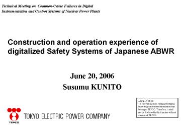
Title:
June 20, 2006
Description:
Fire, Seismic, Ambient Temperature etc. Error on Detail Design Phase ... RPV water level (large display panel) - RPV pressure (large display panel) ... – PowerPoint PPT presentation
Number of Views:24
Avg rating:3.0/5.0
Title: June 20, 2006
1
Technical Meeting on Common-Cause Failures in
Digital Instrumentation and Control Systems of
Nuclear Power Plants
Construction and operation experience of
digitalized Safety Systems of Japanese ABWR
- June 20, 2006
- Susumu KUNITO
Legal Notice This documentation contains
technical knowledge and secret information
that belong to TEPCO. Therefore, it shall not be
disclosed to third parties without consent of
TEPCO.
2
Contents
- History
- Feature of digital safety system for K-6/7
- Consideration on design
- Quality Assurance including VV and several
tests - Consideration for avoiding CCF
- Operating Experience
- Conclusion
3
Application of Digital System in TEPCO BWRs
'70s '80s
'90s
ITEM DATE
3D-CORE PERFORMANCE CAL.
(1)PROCESS COMPUTER (2)REACTOR POWER
REGULATOR (3)PLANT AUX.SYSTEM
CONTROL (4)NEUTRON MONITORING RADIACTION
MONI. (5)SAFETY SYSTEM (6)RADIO-ACTIVE WASTE
PROCESSING SYSTEMS
CORE PERFORMANCE CALCULATION
PLANT AUTOMATION
DIGITAL EHC
CR CONTROL
NON-SAFETY SYSTEM
PLANT WIDE DIGITAL SYSTEM
CF/CD
OFF GAS
NEUTRON MON.
RADIO. MON.
RADIO-ACTIVE WASTE PROCESSING SYSTEM
SEQUENCE CONTROL
MINI.COMPUTER
4
Kashiwazaki-Kariwa Units 6 and 7
-
Unit 6 Unit 7 - Rated core thermal power
3,926 MWt - Rated generator power
1,356 MWe - Start of construction Sep.,
1991 Feb., 1992 - COD
Nov., 1996 July, 1997
1st Concrete Pouring ? F/L 37M
37.5M
5
Main Control room of Units No.6 and 7
Unit No.6
Unit No.7
Alarm Windows
Large Display Panels
Shift Manager
Main Control Console
6
Configuration of ABWR IC System
Multi-Plexing Line
Cable
MAIN CONTROL
CCU
PANEL
Communication Control Unit
ALARM
ALARM
SYSTEM
SYSTEM
PLANT
From Control Units
PLANT
COMPUTER
LEVEL
SYS.
(Large scale computer sys,
µ-P
sys.)
From Local Signals
PROCESS
FLUX
Rx. AUX
RAD.
APR
MONITOR
ECCS
RCIS
FDWC
RFC
MONITOR
LOGIC
SYSTEM
ING
ING
LEVEL
(µ-P
sys.)
CONTROL
RMU
VALVE
RMU
RMU
EQUIPMENT
RMU
TURBINE
LEVEL
GEN
RMU
INVERTER
CONDENSER
ECCS
INTERNAL
PUMP
PUMP
FMCRD
FEEDWATER
FW
CONDENSATE
RMU
PUMP
HEATER
PUMP
K-6 was supplied by Toshiba Hitachi GE K-7
was supplied by Hitachi Toshiba GE
7
The Configuration of RPS
RMU
DTM
TLU
OLU
Sensor
LD
LD
?
?
Application Program
D/O
To LD of Div.1
Network CTL
Network CTL
A/I
2 out of 4 Logic
LD
LD
LD
LD
?
?
?
?
Div.1
LD
LD
Form TLU of Other Div.
?
?
Manual Scram SW
Network CTL
A/I
To TLU of Other Div.
Div.2
Trip Solenoid For Scram
Network CTL
A/I
Div.3
Network CTL
A/I
Div.4
8
The Configuration of ESF
Sensor RMU DTM
SLU-1
To Actuator
RCIC RHR(A) ADS(A)
RMU
D/O
Network CTL
Network CTL
A/I
RMU
SLU-2
Div.1
SLU-1
HPCF(B) RHR(B) ADS(B)
To Actuator
RMU
D/O
A/I
Network CTL
Network CTL
RMU
SLU-2
Div.2
SLU-1
To Actuator
D/O
RMU
A/I
Network CTL
Network CTL
HPCF(C) RHR(C)
RMU
SLU-2
Div.3
D/O
Network CTL
A/I
Network CTL
Div.4
9
Number of Components
RPS/MSIV 4 4
ESF 4 32
Component DTM TLU(SLU)
DIV.1 3 DIV.2 3 DIV.3 2 On Operator Console
4 On 4 Control Panel
Flat Display
Control Panel
4 4 1500 points 4500 points
3 17 5000 points 30000 points
RMU PI/O
Transmission Data
10
Consideration on Software Design
Simple Logic - Mostly described by AND,
OR, and NOT components
Periodic Execution - Simple software structure
No Interruption in external signal processing -
Simple software structure
Static Memory allocation - Simple software
structure
Flow-diagram-like Symbolic Language (POL) -
Easy to program and verify POL Problem
Oriented Language
11
Adoption of POL
(1) Listing type software languages such as
FORTRAN,C etc. take much time and
manpower to utilize.
(2) With POL software design and development can
be done visually.
(3) Particularly in the system logic test
(Validation Test), every path of the
software could be easily verified by
checking the status information on the
maintenance tool.
12
Software diagram and POL (Problem Oriented
Language)
Operation Number
00
Software Diagram
00
(D0016)
01
AND
02
Operation Code
(D0017)
(D0896)
(D0018)
OR
(D0019)
Variable Number
(D0016)
Extraction of Program Data
00
AND
01
02
OUT
OR
D0896
D0018
D0016
NOT0017
D0019
Extracted Program Data
Rearrangement of the Extracted Program
Data According of Order of Calculation
Rearrangement of Variable number according to the
rule, which is uniquely defined for
each operation code
OR
OUT
AND
D0018
D0016
D0896
D0019
NOT
D0017
Execution
13
Necessity of VV of Software
Compare Potential Risk of Common Mode Failure
(Analog System vs Digital System) - General
Understanding, Not Specific to K-6/7 -
RISK
EVALUATION
Equal
Hardware
Common Mode Failure - Fire, Seismic, Ambient
Temperature etc.
Software
Equal
Error on Basic Design Phase - Error of Scram
Logic and Set Point etc.
Equal
Error on Detail Design Phase - Error of Drawing
and Diagram etc.
More
Error on Programming
As for applying digital technology, VV is
required to avoid Common Mode Failure.
Equal Digital system has equal risk
potential. More Digital system has more risk
potential.
VV Verification Validation
14
Procedure to achieve highly Reliable System-1/2
System Requirement (EP,JEAG et al.)
Verification-1
System Specification
Verification-2
Equipment Specification Interlock Block Diagram
Hardware Design (ECWD)
Verification-3/4
Software Design
POL Coding ( CAD System)
Component Procurement
?De-compile Check
Parts Screening
Verification-5
Cabinet Assembly
Floppy Disk
Software Loading
15
Procedure to achieve highly Reliable System-2/2
Validation
Factory Tests
? Semi-dynamic simulationTests for
safety-related system
Shipping
Visual Inspection I/O Wiring Inspection I/O
Characteristic Tests System Logic Tests Response
Time Tests Single Failure Tests
Installation at site
Installation Tests
Reassemble Tests I/O Wiring Check Digital I/O
Check Analog I/O Check
Pre-operation Tests
METI Inspection
Interlock Tests Annunciation Tests Actuator
Tests Protection Device Tests Combination Tests
Fuel Loading
Heat-up Tests
METI Inspection
? Special Tests only for K-6/7 Digital
Safety-Related System
Commercial Operation
Additional Procedure for Safety-Related System
16
TEPCO Practice of Design Approval, Witness
Documents of Safety Related System
Design Approval
Factory Test Witness
System Specification
Execute
Execute
Equipment Specification
Interlock and Annunciation function test is
sample inspection and data inspection
Interlock Block Diagram
Verification -1
Execute
Elementary Control Wiring Diagram
Execute
Verification -2
Execute
Software Diagram
Display confirmation test is data inspection
Execute
FD(Flat Display) forms
Verification -3/4
Document Examination Point No difference from
Upper Document Confirmation of difference from
System requirements, Design Review, Previous
Plant, Between K6 and K7
17
Example of VV document (Veri-2)
18
Experience of K-6/7 VV
ltExperiencegt V V is clear and feasible with
POL. Veri-3/4Easy to compare and verify IBD
and software diagram. Validation Graphical
Tool is very useful to perform VV.
POL(Problem Oriented Language) is very effective.
Graphical Tool is necessary for performing VV
definitely.
In the system logic test in the validation test,
every path of the POL software could be validated
by checking the status information on the
maintenance tool display. (It might be
difficult to check the every path of the listing
type software.)
19
Evaluation of VV Activities
Effectiveness
No major discrepancy was found.
Work-force
- Documentation several thousands pages - Total
Man-hour a few thousands man-days/plant
Improvement for following construction
- to promote Software Modularization - to reuse
the software verified already
Decrease VV activities load
20
Development Process of Digital Safety System
ITEM
86
87
88
89
90
91
92
93
94
95
Product Schedule (K-6)
Development
Manufacture Test
Design
Shipment
Major RD Activities
Guideline Setting (Application of Digital
Computers to Safety Systems JEAG 4609)
Issued
Cooperative Research by TEPCO and the JV companies
Actual Proof Examination in NUPEC
21
JEAG 4609 (Guideline on Application of Digital
Computers to Safety Systems)
JEAG Industry Standard (JEA (Japan Electric
Association) Guideline
Objective Identify Minimum Requirements of
Safety Digital Controls Requirements -
Almost Same as I.EEE 7-4,3,2 - Focus on
Qualification Process - Requires
to clarify design and manufacturing
process to ensure
traceability of design and manufacturing of S/W
to carry out VV
(also shows typical VV process)
to assign verifiers among other
than designers to document
VV results
22
Cross Check of IBD between K-6 and K-7
Software Diagram made on CAD according to
IBD(Interlock Block Diagram) is compiled and
installed to controller through maintenance tool.
So propriety of software depends on IBD.
Purpose Correction of mistake at basic design
stage Standardization of SSLC Logic
Enhance reliability through performing above two
evaluation
Result Simplify Interlock even if right
logically Standardize manual initiation
logic of ESF etc.
23
Semi-Dynamic Simulation Test
From the viewpoint that the system is the
first digital Reactor Protection System, we
confirm the validity of the system by simulating
the changes of the process values.
- Prepare the simulator which simulates the
changes of the parameters used in the safety
analysis. (LOCA and so on)
- Input the signals from the simulator to the
digital controller, and record the
corresponding system behavior by the recorders.
- Verify whether the system works as expected or
not.
24
Results of Semi-Dynamic Simulation Test
Example for the failure of reactor pressure
controlling device
Input signal
Digital Input
Analog Input
Output signal
Digital Output
25
Semi-Dynamic Simulation Test Results
Item
Test Case
Results
RPS 6650 tests
All Good
Dynamic Transient Test
ESF 2320 tests
All Good
Random Input 5240 tests
Random Input Test
All Good
26
Transition of US Digital Safety System Design
(Diversity)
Function added according to US ABWR Design
Issued - CUW Line Isolation with proper Valve
Status display -RCIC Steamline Isolation with
proper Valve Status display -HPCF(C) Initiation
with proper System Status display
TEPCOs design is same above.
27
Hardwired Backup for SSLC
Defence in Depth Design
Control - Manual scram (main
console) - Manual MSIV closure (main
console) - CUW line isolation (back
panel) - RCIC steam line isolation
(back panel) - HPCF(C) initiation
(back panel) Display - RPV water level
(large display panel) - RPV pressure
(large display panel) - MSIV status
(large display panel) - CUW isolation valve
status (back panel) - RCIC isolation
valve status (back panel) - HPCF(C)
status (back panel)
(Added After US ABWR Design Issued)
28
Diversity in Reactor Protection System
Manual Channel Trip SW
Manual SCRAM SW
Software Logic Unit
B
A
2/4
?
?
2/4
2/4
2/4
?
?
?
?
?
?
Hardwired Logic
Division I - IV
Division I - IV
Solenoid (A)
Solenoid (B)
SCRAM Pilot Valve
29
Failure experienced on K-6/7 digital safety system
- More than 10 years have passed since K-6/7
started commercial operation. - As for the failure on digital safety system,
- No severe failure caused by design occurred.
- One time error (non-repetitive) occurred several
times - e.g. One SLU failure was detected by
self-diagnosis function. - Parity error on some register was
found to have occurred. - Initialization was done and after that
there is no problem. - - We record every non-conformity on the data base
and utilize for next generation.
30
Conclusion
- - Long experience of Non-Safety system usage
contributed - very much to success of digital safety system
adoption in K-6/7. - - Design standardization and existing verified
software - application is also effective from the safety
and economical - viewpoint.
- Its also very effective to use the software
feasible for VV such as graphical language like
POL. - No problem was raised on the extent of suitable
backup measures against CMF. - Same design was also adopted for following
ABWRs - Hamaoka unit No.5 (COD Jan. 05)
- Shika unit No.2 (COD Mar. 06)
31
Thank you for attention!
Recommended
CrystalGraphics Presentations


