Malfunction Indicator Lamp - PowerPoint PPT Presentation
1 / 8
Title: Malfunction Indicator Lamp
1
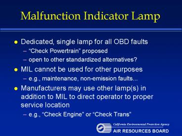
Malfunction Indicator Lamp
- Dedicated, single lamp for all OBD faults
- Check Powertrain proposed
- open to other standardized alternatives?
- MIL cannot be used for other purposes
- e.g., maintenance, non-emission faults...
- Manufacturers may use other lamp(s) in addition
to MIL to direct operator to proper service
location - e.g., Check Engine or Check Trans
2
MIL and Fault Code Logic
- OBD requires statistical fault detection
- first fault detection requires pending code
- fault detection on two consecutive driving cycles
requires confirmed code and MIL on - MIL extinguished when
- three consecutive driving cycles occur with no
fault detected (monitor runs and passes) or - scan tool used to clear codes
- Confirmed Codes
- stay in memory for 40 warm-up cycles after MIL
extinguished
3
Driving Cycle Definition
- Basic Definition
- Engine start, monitor runs once, engine shut-off
- Heavy-duty has unique operator habits
- Engine may be running on a single start for
hours, days, or even weeks at a time - Alternate definition needed
- Monitors required to run only once-per-driving
cycle would be re-enabled after four hours of
continuous operation
4
Roadside Inspection Integrity
- OBD system must be able to be used robustly in a
roadside inspection - Two elements used to detect drivers attempting to
clear codes without repair - Readiness codes (identify if major monitors have
run since code clear) - Permanent DTCs (identify if most recent MIL-on
fault has run since code clear) - can only be
erased by the OBD system itself, not by battery
disconnect or scan tool
5
OBD Performance Tracking
- In-use performance
- Requires on-board computer to keep a count of how
often each major monitor has run and could have
detected a fault - Requires a separate counter to record how often
the vehicle has been operated
6
OBD Performance Tracking (cont.)
- Ratio of two counters indicates monitor frequency
- Presently no minimum ratio or enforcement process
based solely on this ratio - 2010 OBD regs will start using this ratio as part
of the requirements (e.g., minimum ratio of
0.100)
7
Engine Operation Tracking
- Requires on-board computer to log the amount of
- total engine operation
- engine idle
- operation in the NTE zone (speed/torque defined)
- each individual AECD activated
- Only log AECDs that
- reduce emission control effectiveness (i.e.,
cause measurable increase in emissions) and - are not activated during emission certification
testing
8
OBD Communication Protocol
- Original proposal
- Single protocol (but undetermined as to which
one) - Revised proposal
- Allow use of SAE J1939 or ISO 15765
- However, must use one or the other for all
required OBD communications - cannot use ISO 15765 protocol with J1939
connector - cannot have some modules on a truck use J1939 and
others on the same truck use ISO 15765 - ISO 15765 restricted same as LDV
- 500k only and max 12 Volts at connector

