
ADVENT - PowerPoint PPT Presentation
1 / 17
Title: ADVENT
1
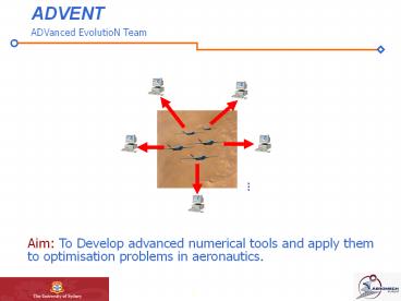
ADVENT
ADVanced EvolutioN Team
- Aim To Develop advanced numerical tools and
apply them to optimisation problems in
aeronautics.
2
Outline
- Why are we interested in evolutionary
optimisation? - How does it work?
- What have we solved so far?
- We are we going now?
3
Why Evolution?
- Traditional optimisation methods will fail to
find the real answer in most real engineering
applications. - Techniques such as Evolution Algorithms can
explore large variations in designs. They also
handle errors and deceptive sub-optimal solutions
with aplomb. - They are extremely easy to parallelise.
- They can provide optimal solutions for single and
multi-objective problems.
4
Some Applications to Date
- Evolution is being applied in thousands of fields
right now. Some examples in aviation are - Whole wing design for drag reduction.
- Radar cross-section minimisation.
- Whole turbofan layout and blade design.
- Formation flight optimisation for maximum
engagement success. - Autopilot design and trajectory optimisation.
- As well as combinations of the above.
5
What Are Evolution Algorithms?
- Based on the Darwinian theory of evolution ?
Populations of individuals evolve and reproduce
by means of mutation and crossover operators and
compete in a set environment for survival of the
fittest.
Evolution
Crossover
Mutation
Fittest
- Computers perform this evolution process as a
mathematical simplification. - EAs move populations of solutions, rather than
cut-and-try one to another. - EAs applied to sciences, arts and engineering.
6
Hierarchical Topology-Multiple Models
Model 1 precise model
Exploitation
- We use a technique that finds optimum solutions
by using many different models, that greatly
accelerates the optimisation process. - Interactions of the layers solutions go up and
down the layers. - Time-consuming solvers only for the most
promising solutions. - Asynchronous Parallel Computing
Model 2 intermediate model
Model 3 approximate model
Exploration
7
Results So Far
Evaluations CPU Time
Traditional 2311 224 152m 20m
New Technique 504 490 (-78) 48m 24m (-68)
- The new technique is approximately three times
faster than other similar EA methods.
- A testbench for single and multiobjective
problems has been developed and tested
- We have successfully coupled the optimisation
code to different compressible and incompressible
CFD codes and also to some aircraft design codes - CFD
Aircraft Design - HDASS MSES XFOIL
Flight Optimisation Software (FLOPS) - FLO22 Nsc2ke
ADS (In house)
8
Results So Far (2)
- Constrained aerofoil design for transonic
transport aircraft ? 3 Drag reduction
- UAV aerofoil design
- -Drag minimisation for high-speed transit and
loiter conditions. - -Drag minimisation for high-speed transit and
takeoff conditions.
- Exhaust nozzle design for minimum losses.
9
Results So Far (3)
- Three element aerofoil reconstruction from
surface pressure data.
- UCAV MDO
- Whole aircraft multidisciplinary design.
- Gross weight minimisation and cruise efficiency
- Maximisation. Coupling with NASA code FLOPS
- 2 improvement in Takeoff GW and Cruise
Efficiency
- AF/A-18 Flutter model validation.
10
An Example Aerofoil Optimisation
Property Flt. Cond. 1 Flt Cond.2
Mach 0.75 0.75
Reynolds 9 x 10⁶ 9 x 10⁶
Lift 0.65 0.715
- Constraints
- Thickness gt 12.1 x/c (RAE 2822)
- Max thickness position 20 55
To solve this and other problems standard
industrial flow solvers are being used.
Aerofoil cd cl 0.65 cd cl 0.715
Traditional Aerofoil RAE2822 0.0147 0.0185
Conventional Optimiser Nadarajah 1 0.0098 (-33.3) 0.0130 (-29.7)
New Technique 0.0094 (-36.1) 0.0108 (-41.6)
- For a typical 400,000 lb airliner, flying 1,400
hrs/year - 3 drag reduction corresponds to 580,000 lbs
(330,000 L) less fuel burned.
- 1 Nadarajah, S. Jameson, A, " Studies of the
Continuous and Discrete Adjoint Approaches to
Viscous Automatic Aerodynamic Shape
Optimisation," AIAA 15th Computational Fluid
Dynamics Conference, AIAA-2001-2530, Anaheim, CA,
June 2001.
11
Aerofoil Characteristics cl 0.715
Aerofoil Optimisation (2)
Aerofoil Characteristics cl 0.65
Delayed drag divergence at high Cl
Delayed drag divergence at low Cl
Aerofoil Characteristics M 0.75
Delayed drag rise for increasing lift.
12
Second Example UCAV Multidisciplinary Design
Optimisation - Two Objective Problem
Cruise efficiency maximisation and gross weight
minimisation
Engine Start and warm up
13
UCAV MDO Design (2)
14
UCAV MDO-MO (2) Comparison
Variables Pareto Member 0 Pareto Member 3 Pareto Member 7 Nash Equilibrium
Aspect Ratio 4.76 5.23 5.27 5.13
Wing Area (sq ft) 629.7 743.8 919 618
Wing Thickness (t/c) 0.046 0.050 0.041 0.021
Wing Taper Ratio 0.15 0.16 0.17 0.17
Wing Sweep (deg) 28 25 27 28
Engine Thrust (lbf) 32065 32219 32259 33356
Gross Weight (Lbs) 57540 59179 64606 62463
MCRUISE.L/DCRUISE 22.5 25.1 27.5 23.9
15
Outcomes
- The new technique with multiple models Lower
the computational expense dilemma in an
engineering environment (three times faster) - Direct and inverse design optimisation problems
have been solved for one or many objectives. - Multi-disciplinary Design Optimisation (MDO)
problems have been solved. - The algorithms find traditional classical results
for standard problems, as well as interesting
compromise solutions. - In doing all this work, no special hardware has
been required Desktop PCs networked together
have been up to the task.
16
What Are We Doing Now?
- A Hybrid EA - Deterministic optimiser.
- EA MDO Evolutionary Algorithms Architecture
for Multidisciplinary Design Optimisation - We intend to couple the aerodynamic
optimisation with - Aerodynamics Whole wing design using Euler
codes. - Electromagnetics - Investigating the tradeoff
between efficient aerodynamic design and RCS
issues. - Structures - Especially in three dimensions
means we can investigate interesting tradeoffs
that may provide weight improvements. - And others
Wing MDO using Potential flow and structural FEA.
17
THE END
Questions?
Recommended
CrystalGraphics Presentations


![get [PDF] Download Gilmore Girls: The Official Advent Calendar PowerPoint PPT Presentation](https://s3.amazonaws.com/images.powershow.com/10064934.th0.jpg?_=202406261010)
![❤[PDF]⚡ Supernatural: The Official Advent Calendar PowerPoint PPT Presentation](https://s3.amazonaws.com/images.powershow.com/10081227.th0.jpg?_=20240718018)


