
Learning Objectives: - PowerPoint PPT Presentation
1 / 19
Title:
Learning Objectives:
Description:
... the exploded isometric view of the Pedestal Bearing assembly created in Tutorial ... the Drawing mode, select the Pedestal Bearing as the model, and ... – PowerPoint PPT presentation
Number of Views:48
Avg rating:3.0/5.0
Title: Learning Objectives:
1
CAD 3D Solid Modeling Pro/ENGINEER
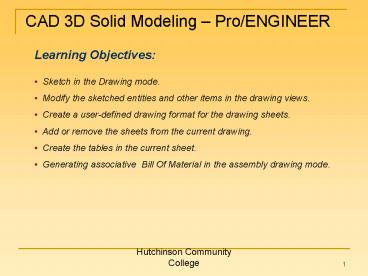
Learning Objectives
- Sketch in the Drawing mode.
- Modify the sketched entities and other items in
the drawing views. - Create a user-defined drawing format for the
drawing sheets. - Add or remove the sheets from the current
drawing. - Create the tables in the current sheet.
- Generating associative Bill Of Material in the
assembly drawing mode.
2
CAD 3D Solid Modeling Pro/ENGINEER
- Sketching in the Drawing Mode
- Sketching can be done by using the Sketch menu
in the menu bar or the tool buttons available in
the Drawing Sketcher Tools toolbar in the Right
Toolchest. - The tools available in the Drawing Sketcher
Tools toolbar and the options available in the
Sketch menu that are used to sketch in the
Drawing mode are discussed next.
- Select Items
- Line
3
CAD 3D Solid Modeling Pro/ENGINEER
- Circle
- Arc
- Chain
- Sketching Using References
4
CAD 3D Solid Modeling Pro/ENGINEER
- Modifying the Sketched Entities
- There are various options to modify the
sketched entities that are termed as draft
entities. - The operations or the modifications that can be
applied on the draft entities in Pro/ENGINEER
Wildfire 2.0 are discussed next.
- Trimming the Draft Entities
- The sketched or draft entities can be trimmed
by choosing Edit gt Trim from the menu bar. - When you choose this option, the cascaded menu
is displayed, as shown in the figure. - The options in this menu are
Cascaded menu of Trim option in Edit menu
- Divide at Intersection
- Bound
- Length
- Divide by Equal Segments
- Increment
- Corner
5
CAD 3D Solid Modeling Pro/ENGINEER
- Transforming the Draft Entities
- To translate or move the draft entities, choose
Edit gt Transform. - The cascaded menu is displayed as shown in the
figure. - The options in this cascaded menu are given
below.
Cascaded menu of Translate option in Edit menu
- Translate
- Translate and Copy
- Rotate
- Rotate and Copy
- Rescale
- Mirror
- Stretch
The GET VECTOR menu with GET POINT submenu
6
CAD 3D Solid Modeling Pro/ENGINEER
- Grouping the Entities
- A draft entity can be grouped with other draft
entity, with a note, a geometric tolerance
(Gtol), or a dimension. - In Pro/ENGINEER, the note, gtol, and dimensions
are called detail items. - After grouping the draft entities, any
operation applied on any one of them is applied
to the grouped entity also. - The options to group can be invoked by choosing
Edit gt Group. The cascaded menu is displayed as
shown in the figure.
- Draft Group
- Set Default Relate View
- Unset Default Relate View
- Relate to View
Cascaded menu of Group option in Edit menu
- Relate to Object
- Unrelate
7
CAD 3D Solid Modeling Pro/ENGINEER
- Drafting Using the Drawing Views
- You can use the generated drawing views to
create an entity or the whole drawing view. - To use a generated drawing view, choose Sketch
gt Edge. - The cascaded menu is displayed with two
options Use and Offset.
- Use
- The Use option is selected to draw a copy of
the selected edge in the drawing view. - This option will be available only when you
have at least one drawing view in the current
drawing sheet and if it is selected.
- Offset
- When you choose this option from the cascaded
menu, the OFFSET OPER menu is displayed as shown
in the figure on the next slide, there are two
options in this menu. - The Single Ent option is used to select a
single entity from the drawing view. - The Ent Chain option is used to select a chain
of entities from the drawing view.
8
CAD 3D Solid Modeling Pro/ENGINEER
The OFFSET OPER menu
- Converting a Generated View to a Draft View
- To convert a generated view to a draft view,
choose Edit gt Convert to Draft Entities from the
menu bar. - After converting a generated view to a draft
view, all the objects in the view are converted
to individual entities. - This option is available only when the drawing
view is selected. - When you choose this option, the SNAPSHOT menu
is displayed, as shown in the figure on the right
side.
The SNAPSHOT menu
9
CAD 3D Solid Modeling Pro/ENGINEER
- User-Defined Drawing Formats
- Sometimes you may need to create a user-defined
drawing format that is specifically designed as
per your requirements. - Choose the Create a new object button to
display the New dialog box. - In this dialog box, select the Format radio
button from the Type area and then specify the
name of the format in the Name edit box to
proceed for creating the user-defined format. - When you choose OK, the New Format dialog box
is displayed.
The New Format dialog box
10
CAD 3D Solid Modeling Pro/ENGINEER
- Figure A shows a user-defined format created
using the A4 size sheet. - This format consists of the user-defined title
block. - Figure B shows the drawing views generated on
the user-defined format.
Figure A User-defined format
Figure B Drawing views generated using a
user-defined format
11
CAD 3D Solid Modeling Pro/ENGINEER
- Retrieving the User-Defined Formats in the
Drawings
- Once you have created the user-defined
formats, you can use them in the Drawing mode as
sheets for generating the drawing views. - To retrieve the user-defined format, select
the Empty with format radio button and choose the
Browse button from the New Drawing dialog box to
invoke the Open dialog box. - A folder named System Formats will be
displayed in the Open dialog box. - Some predefined formats are given in this
folder. - You can retrieve these predefined formats or
browse the location where you have saved the
user-defined format created earlier.
12
CAD 3D Solid Modeling Pro/ENGINEER
- Adding and Removing Sheets in the Drawing
- To add sheets in the current drawing, choose
Insert gt Sheet from the menu bar. - A new sheet is displayed on the screen.
- At the bottom of the screen, the sheet number
is displayed. - You can generate various views of a model on
multiple sheets. - All these drawing views on different sheets are
contained in a single drawing file. - To remove sheets from a drawing, choose Edit gt
Remove gt Sheets from the menu bar. - The Message Input Window is displayed.
- Enter the sheet number that you want to remove.
13
CAD 3D Solid Modeling Pro/ENGINEER
- Creating Tables in Drawing Mode
- You can easily create any kind of tabular
representation in Drawing mode by using the
options available in the cascaded menu that is
displayed when you choose Table gt Insert from the
menu bar. - The cascaded menu is displayed, as shown in
the figure on the top.
Cascaded menu
- Table Option
- Table From File Option
- Column Option
- Row Option
The TABLE CREATE submenu
14
CAD 3D Solid Modeling Pro/ENGINEER
- Using the Assembly Bill Of Material in the
Drawings
- The Bill Of Material (BOM) is a representation
of the components and their parameters that are
used in the assembly. - Steps to generate the BOM and Balloons in the
Drawing mode are
- Creating the Table for BOM
- Setting the Repeat Region
- Creating the Column Headers
- Assigning the Report Symbols in the Repeat
Region
- Generating the Exploded Drawing View
- Setting the No Repeat Option
- Generating Balloons
15
CAD 3D Solid Modeling Pro/ENGINEER
- Tutorial 1
In this tutorial you will create a format of size
A and add the title block in the format. Then you
will retrieve the format in the Drawing mode and
generate the exploded isometric view of the
Pedestal Bearing assembly created in Tutorial 2
of Chapter 9. Also, add the assembly Bill of
Material and the Balloons to the drawing view as
shown in Figure A. (Estimated
time 45 min)
Figure A The drawing view of the assembly showing
the BOM and balloons
16
CAD 3D Solid Modeling Pro/ENGINEER
- Open a new file in the Format mode, create the
format of the drawing, and add the title block in
the format as shown in Figure B.
- Save the format file and then close it.
Figure B The title block
17
CAD 3D Solid Modeling Pro/ENGINEER
- Open a new drawing file in the Drawing mode,
select the Pedestal Bearing as the model, and
retrieve the format that you had created.
- Generate the exploded drawing view as shown in
Figure C.
Figure C Exploded isometric view of the assembly
18
CAD 3D Solid Modeling Pro/ENGINEER
- Create and save the BOM. Then place the BOM in
the drawing view.
- Edit the text in the BOM.
- Enter the text in the title block and add
balloons to the drawing view. The drawing sheet
after placing the BOM and adding the balloons
should look similar to the one shown in Figure D.
- Save the drawing and then close the window.
19
CAD 3D Solid Modeling Pro/ENGINEER
Figure D The drawing view of the assembly showing
the BOM and title block
Recommended
CrystalGraphics Presentations


