Flow through borders and vertices in foam drainage - PowerPoint PPT Presentation
1 / 1
Title:
Flow through borders and vertices in foam drainage
Description:
Drainage in a foam refers to the flow of fluid through the network of liquid ... one may want to increase drainage (fractionation) or suppress it (Guinness! ... – PowerPoint PPT presentation
Number of Views:57
Avg rating:3.0/5.0
Title: Flow through borders and vertices in foam drainage
1
Flow through borders and vertices in foam
drainage L. Alonso1, G. Bradley2, S.J. Cox1, S.
Hutzler1, N. Kern1, D. Weaire1 1Department of
Physics, Trinity College, Dublin,
Ireland 2Trinity Centre for High Performance
Computing, Trinity College, Dublin, Ireland
Drainage in a foam refers to the flow of fluid
through the network of liquid channels
constituting the continuous phase of the foam
structure. This occurs in all liquid foams
subject to external pressure or body forces.
Depending on the application, one may want to
increase drainage (fractionation) or suppress it
(Guinness!). The drainage rate depends on many
factors, a major one of which is the geometry of
the elements (Plateau borders, vertices) through
which the fluid flows.
Once we have determined the static shape, two
questions arise
How does the shape affect the flow ? How does the
flow affect the shape ?
We start by considering the fixed shape of the
elements, calculated using the Surface Evolver,
as non-slip channels through which the liquid
flows. This allows us to find the correction to
drainage theory due to the flow. There are two
groups of elements, those in the bulk of the foam
and those at the edges which are confined to lie
against a plane wall.
Flow through fixed geometry
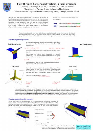
In a monodisperse foam the radius of curvature r
of the Plateau borders is constant everywhere.
This also fixes the cross-sectional area of the
Plateau borders Therefore the wall borders
contain significantly more fluid than those in
the bulk. The resistance of a border to flow is
characterised by a numerical constant ? (e.g.
?25 for a circular tube). For the bulk and wall
borders the values differ only slightly
Therefore the flow down the walls of a
contained foam could have a large influence on
the drainage behaviour.
Bulk Plateau border
Wall Plateau border
AB cB r2 (with cB 0.161)
AW cW r2 (with cW 0.429)
?W 50.7
?B 49.8
Wall vertex
Bulk vertex
The bulk vertex corresponds to the junction of
four equal Plateau borders whereas the wall
vertex is the junction of three equal wall
Plateau borders and one bulk border. Each border
has equal length L and radius of curvature r. The
total liquid volume is a correction to the volume
of these four borders of the form where The
values of A are given by the Plateau border
geometry and Evolver simulations give the
corrections B due to the vertex.
V/L3 A (r/L)2 B (r/L)3 .
A 4cB and B0.456
A3cW cB and B1.438
A drainage theory based only upon the flow
through the borders can be extended to include
the bulk vertices most crudely by the use of
length corrections. We can represent the extra
volume due to a vertex by lengthening each of the
adjacent borders. In the same way, the change in
viscous dissipation due to the flow through the
vertex can be accommodated by a negative length
correction. The two opposing corrections are of a
similar magnitude, explaining why the standard
(bulk) drainage theory works so well without
including vertices. For the wall vertices, the
idea of a length correction is not so
straightforward, since all four borders are no
longer equal.
Flow through deformable geometry
We can improve upon the above calculation by
allowing the structure to deform in response to
the viscous stresses induced by the flow. This is
achieved using an iterative scheme between a
surface minimisation package (Evolver) and a flow
solver (Fluent). For a single, bulk Plateau
border, this shows how the cross-section varies
along the pressure gradient. To do the same for
the other elements of interests is now a
straightforward extension of the method.
Iterative procedure (o) Static structure
(Evolver) (i) Flow field (Fluent) (ii)
Stresses (Fluent) (iii) Deformation (Evolver)
Acknowledgements GB wishes to thank K. Brakke
for assistance. This research was supported by
the Prodex programme of ESA. LA was supported by
a TCD HPC fellowship and NK was supported by a
Marie Curie fellowship.


