Maxwell, time harmonic, transversetoz - PowerPoint PPT Presentation
1 / 17
Title:
Maxwell, time harmonic, transversetoz
Description:
EE 325, Dept. of ECE, Univ. of Texas at Austin. plane wave reflections ... what happens if we add the reflected and transmitted powers? ... – PowerPoint PPT presentation
Number of Views:29
Avg rating:3.0/5.0
Title: Maxwell, time harmonic, transversetoz
1
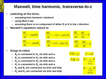
Maxwell, time harmonic, transverse-to-z
- collecting all the terms,
- assuming time harmonic solutions
- using Ohms law
- assuming there is no component of either E or H
in the z direction - Maxwells equations reduce to
- things to notice
- Ey is connected to Hx via d/dz and w
- Ex is connected to Hy via d/dz and w
- Hy is connected to Ex via d/dz and w
- Hx is connected to Ey via d/dz and w
- Ey and Ex are connected via d/dx and d/dy
- Hy and Hx are connected via d/dx and d/dy
2
Uniform plane wave solution to Maxwells equations
- the complete, time harmonic solution is
- g is called the complex propagation constant
- direction of propagation
3
Plane waves and boundaries
- we have found the TEM traveling wave solution
to Maxwells equations that would work in a world
that is made on one and only one material - what would happen if there were a simple
dielectric interface, i.e., half the world is
filled with e1, and half is e2 ? - we must still satisfy boundary conditions at the
interface between the materials - in anticipation of what we need to solve this
problem, lets assume now that as a result of
the incident wave there will be a transmitted
wave and a reflected wave
medium 1 er1 mr1 s1
x
medium 2 er2 mr2 s2
y
z
4
Plane waves and boundaries
- as a result of the incident wave there will be a
transmitted wave and a reflected wave
x
medium 1 er1 mr1 s1
y
medium 2 er2 mr2 s2
z
5
Fields at the interface
- the total fields at the interface between the two
materials (i.e., at z0) are - infinitesimally to the left of the interface
- infinitesimally to the right of the interface
- since the fields are tangential to the interface,
and were assuming there is no surface current in
this problem, the fields must be CONTINUOUS
across the interface - so we have two unknowns, Ereflect (Ex1o-) and
Etransmit (Ex2o)
6
Transmitted and reflected fields
- two unknowns, two equations
7
Reflection coefficient
- we now have simple relation that gives the ratio
of the reflected electric field to the incident
electric field - the reflection coefficient G is
- for our assumed coordinate system the sign of G
will tells us which way the reflected electric
field points - Eincident pointed in the x direction
- if G is positive, then Ereflect also points in
the x direction - if G is negative, then Ereflect points in the -x
direction
8
Transmission coefficient
- recall we had the equation from continuity of
total tangential electric field at the interface,
and we also have the reflection coefficient, so - we define the transmission coefficient t to be
the ratio of the transmitted electric field to
the incident electric field
9
Magnetic fields
- recall we had the simple relation between the
electric and magnetic fields - so we can also define a magnetic field reflection
coefficient - and the transmitted magnetic field is
10
Power flow reflected power
- Poynting vectors at the interface (z 0)
- so the ratio of the incident power to the
reflected power is
11
Power flow transmitted power
- Poynting vectors at the interface (z 0)
- so the ratio of transmitted power to incident
power is
12
Example two lossless dielectrics
- assume the two materials are lossless, s 0, m
mo - so here
- limits
- er1 ltlt er2 ? G -1, t 0
- er1 gtgt er2 ? G 1, t 2
13
Example two lossless dielectrics
- assume the two materials are lossless, s 0, m
mo - lets assume that er1 lt er2
medium 1 e er1eo
medium 2 e er2eo
14
Example two lossless dielectrics, power flow
- assume two lossless materials, s 0, er1 , er2 ,
m mo
15
Example two lossless dielectrics, power
conservation
- what happens if we add the reflected and
transmitted powers?
16
Plane wave applets
- very nice, with ability to vary materials
properties and frequency, includes power flow - reflection at a dielectric interface
http//www.amanogawa.com/archive/Oblique/Oblique-2
.html - index http//www.amanogawa.com/archive/wavesA.htm
l - this site is pretty useful for other things like
transmissions lines - they also have a pretty nice set of lecture slides
17
Power flow transmitted power
- Poynting vectors at the interface (z 0)
- so the ratio of transmitted power to incident
power is


