P1254503583cTreu - PowerPoint PPT Presentation
1 / 1
Title: P1254503583cTreu
1
The optical fibers obtained by liquid crystal
photonic bandgap, Photonic Crystal Fibers
(PCFs) Kr. Panayotov, T. Angelov, H. Naradikian,
B. Katranchev and M. Petrov Institute of Solid
State Physics, Bulgarian Academy of Sciences, 72,
Tzarigradsko Chaussee Blvd, 1784 Sofia,
Bulgaria Corresponding authors e-mail
mpetrov_at_issp.bas.bg
MICROTEXTURAL POLARIZATION ANALYSIS OF
CAPILLARIES INFILTRATED WITH THE NEMATIC E7.
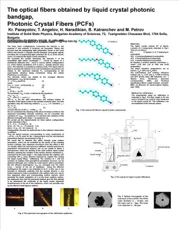
ALIGNMENT STUDY The three basic configurations
concerning the director n, the polarizer P and
analyzer A locations are presented. Taking into
account that the propagating light polarization
(linear in the case) follows the director n
changes and the Mauguin wave-guide regime,
providing the corresponding light extinction (for
E?n), E-the electric vector, we explored the
liquid crystal orientation. We examined the
sample measuring the intensity Itr of the
transmitted light (mean wavelength ? ? 0.5?m) by
means of a photodiode (detected area ? mm2) in
various optical configurations (i.e. of the
mutual orientations of P, A and no - nematic
director easy axis). The intensity is evaluated
in arbitrary units Itr0 means that no light is
reaching the detector at all, and normalization
procedures are related to the maximum intensity
Itro, corresponding to the experimental situation
being considered. Using the Adobe Photoshop, we
selected ?. The intensity values are related to
the averaged effective birefringence ??neff? by
the formula Itr ? Iotr G (?,?)sin2(??2),
(1) where G (?, ?) ?
cos2?? sin2(2?)sin2(???) (2) ? ?
(2?d??)??neff?
(3) and ? ? (P?A), ? ? (no?P).
(4) The parameter
?neff, in turn, is defined by the
equations ?neff ? neff ?no
(5) neff?2 ? sin2?
ne?2 ? cos2? no?2
(6) and ne, no are the main extraordinary and
ordinary indices of refraction of the liquid
crystal in the nematic (uniaxial) state. The
later quantities obey the following relations
?e??o??a, ??n2 therefore ?a ? 2no ?n, i.e. ?n ?
?a ?2no
(7) we have also for LC E7 no ?
1.5185, ?a ? 12. We can summarize the meaning of
the above formulae as follows the measured
transmitted intensity variations can be converted
into variations of ??neff? ? by equations 1-3
and then into variations of the effective
averaged polar angle ? ?by equations 5,6. We
carried out the measurements for three optical
configurations partly indicated in Fig.4 (i) A
? P, no ? P (where G ? 0) (ii) (A ? P) ? 45?, no
? P (where G ? 1?2) (iii) A ? P, (no? P) ? 45?
(where G ? 1). Configuration (iii) must be
preferred due to the optimum observation
conditions. Thus the typical textures
corresponding to some combination of ??(P?A),
??(no?P) used for the I measurement and the
microtextural polarization analysis are presented
in Fig. 4. We would like to interpret this effect
through some surface parameters, which can be
controlled by the nature of the orienting surface
coatings. One important conclusion from this
effect is that we visually detect the
macroprocess (different oriented pictures) by
polarization microtextural analysis, but we are
unable to detect a microprocess which can develop
at the solid surface?liquid crystal interface,
meaning the variation of the surface director
orientation ns, expressed by the polar angle ? -
the angle between the capillary axis coinciding
with no (easy direction imposed by capilary flow
during the liquid crystal filling -
infiltration). The variation of ? with the
variation of capillary tube geometrical
parameters however, can be detected (although
very weakly) by some typical optical parameters
like the effective birefringence ?neff (?),
averaged over the entire cross section of the
set of capillaries. Using the effective
birefringence the angle ? was estimated to be 5?.
In this way, it was possible to determine
explicitly that the nematic director n was indeed
imposed to follows parallelism with capillary
tube axis, due to flow alignment effect and
corresponding surface memory which dominate the
elastic adaptation of n on the inner capillary
surface. We emphasize here that the presented
method give the first attempt to be determined
the uniformity of the liquid crystal alignment
simultaneously in the set of the capillaries,
which was possible only by the effective
birefringence method.
Method for infiltration The experimental setup
for infiltration is indicated in Fig.2. The fiber
length is 50 mm and is located to be vertical,
thus immersed in the liquid crystal E7. The
infiltration was accomplished in the isotropic
phase.


