Superconducting Bearing for use in BalloonBorne Polarimetry - PowerPoint PPT Presentation
1 / 1
Title:
Superconducting Bearing for use in BalloonBorne Polarimetry
Description:
Superconducting Bearing for use in Balloon-Borne Polarimetry. Frank Calma with ... Balloon borne polarimetry experiments such as the SPIDER experiment require ... – PowerPoint PPT presentation
Number of Views:51
Avg rating:3.0/5.0
Title: Superconducting Bearing for use in BalloonBorne Polarimetry
1
Superconducting Bearing for use in Balloon-Borne
Polarimetry
Frank Calma with John Ruhl Dept. of Physics,
CWRU, 10900 Euclid Ave., Cleveland, OH 44106
- TESTING
- The bearing was tested 3 times. Each test
involved using liquid nitrogen to cool the setup,
- while monitoring the temperature using a
thermistor. In two cases, the armature setup was - used to hold the rotor during cool down.
- During the first experiment, the stator was
cooled in open air. The rotor was placed in the - center of the YBCO ring by hand, and tested to
make sure that the rotor levitated properly, - and spun.
- During the second experiment, the rotor and
stator were placed in a vacuum chamber and - cooled by pouring liquid nitrogen along the
bottom of the chamber. The armature assembly - was used to hold the rotor in place during cool
down. At 85K, the arms failed to release. - the vacuum chamber was then re-pressurized so
that the arms could be disengaged manually. - The bearing was reset, and the driving coil was
then actuated. The bearing failed to levitate. - During the third experiment, the rotor and stator
were cooled in open air, but using the full - armature and coil assemblies. The rotor
successfully levitated above the stator. The
driving - coil was engaged, but failed to properly drive
the coil. The coil appears to sit in one - particular orientation. The driving coil is able
to push the rotor approximately 30 degrees in - either direction, but fails to make a full
revolution, and the rotor eventually returns to
its - original state.
Figure 1. Drawing of the incident rays in the
SPIDER experiment, wth the bearing marked
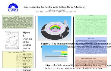
Figure 2 -The prototype superconducting bearing
can be seen in this SolidWorks image. The magnet
(yellow) YBCO hexes (green) and motor and pulley
system (grey) can all be clearly seen.
RESULTS AND CONCLUSIONS The project over
all was a success. The bearing was designed and
manufactured to consider the various requirements
of the system, most notably the cold environment,
the need for low friction, and the lack of
maintenance. Unfortunately, in testing the
project was found to have serious flaws. The
armature system, magnet and superconductor all
had serious flaws in their In future
experiments, all of these systems should be
replaced to meet the standards outlined above for
the SPIDER experiment.
Figure 3 Side view of the superconducting
bearing. The spacing between rotor and stator
can more clearly be seen here.


