The Unified Modelling Language UML - PowerPoint PPT Presentation
1 / 13
Title:
The Unified Modelling Language UML
Description:
set of tightly coupled objects working together for a very ... link, compile, file, library, table, document, executable. The Unified Modelling Language ... – PowerPoint PPT presentation
Number of Views:29
Avg rating:3.0/5.0
Title: The Unified Modelling Language UML
1
1
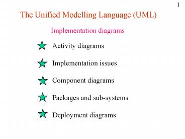
The Unified Modelling Language (UML)
Implementation diagrams
Activity diagrams Implementation
issues Component diagrams Packages and
sub-systems Deployment diagrams
2
The Unified Modelling Language
2
Activity diagrams
Activity diagrams are a cross between Petri-Nets
and Process or Workflow Diagrams and provide a
very user oriented view of system operation. The
main components of such diagrams are -
Process specifications identify individual
steps in processing Workflow
paths define the flow of control or work flow
Swimlanes identify departmental
boundaries or areas of responsibility.
Transitions represent synchronisation
points Decision points if/then/else
branches in work flow Signal and
accept flags provide synchronisation points
between different work flow paths As with
statecharts, these diagrams can be arranged in a
heirarchy.
3
The Unified Modelling Language
3
Example activity diagram
The following represents a simple bespoke
production system - Customer Design
dept. Commercial dept.
Manufacturing
SPECIFY CUST REQ.S
ALLOCATE DESIGNER
ALLOCATE BUILDER
DESIGN PRODUCT
COMPUTE PRICE
not ok
ok
CREATE ORDER
OBTAIN BO ITEMS
BUILD PRODUCT
ASSEMBLE PRODUCT
4
The Unified Modelling Language
4
Example activity diagram
With the inclusion of objects, this becomes
- Customer Design dept.
Commercial dept. Manufacturing
DESIGNER FREE
SPECIFY CUST REQ.S
ALLOCATE DESIGNER
ALLOCATE BUILDER
DESIGNER ALLOC
CUST REQ
DESIGN PRODUCT
COMPUTE PRICE
not ok
ok
CREATE ORDER
PRODUCT
OBTAIN BO ITEMS
ORDER
DESIGNER FREE
BUILD PRODUCT
PRODUCT
PRODUCT COMPLETE
ASSEMBLE PRODUCT
5
The Unified Modelling Language
5
Implementation issues
We have already seen how the class diagram
produced duroing analysis may change
significantly during design as we move from a
conceptual model to an implementation model of
the system. In addition, the following
considerations come to bear and must be
documented - Can reusable components be
created from the defined classes ? How should
classes be separated into packages and
sub-systems ? How should components be deployed
onto the hardware ? What level of concurrency
should there be on individual processors ? How
many processors should there be ? What form
should communication links between processors
take ?
6
The Unified Modelling Language
6
Component diagrams
A component is a reusable, pluggable entity which
usually consists of a set of tightly coupled
objects working together for a very
specific purpose. The component is a black box
(façade pattern) and present a well
defined interface to clients. A component diagram
shows component types and is equivalent to a
class diagram.
ltltcompilegtgt
pluggable interface
ltltcompilegtgt
UML has a number of predefined stereotypes for
components - link, compile, file, library,
table, document, executable
7
The Unified Modelling Language
7
Package Sub-system diagrams
Packages are groups of model entities - which may
be individual classes and/or components. They
are usually logical groupings of components such
as graphics packages or interface components or
maths packages etc. Sub-systems are similar, but
usually represent a functional subset of
the system being built. These groupings are used
- to clarify designs to partition work
guidance system
8
The Unified Modelling Language
8
Deployment diagrams
Deployment diagrams show the way software is
distributed across the available hardware and the
basic hardware architecture in terms
of processors and communication links.
regional computer
ltltWANgtgt
gantry computer
ltltWANgtgt
central computer
9
9
The Unified Modelling Language (UML)
Other topics
Mixin inheritance Multiple inheritance Meta-clas
ses
10
The Unified Modelling Language
10
Mixin inheritance
One of the problems with multiple inheritance is
the ambiguity that arises when there is a common
base class - Here, its unclear what
attributes and methods class D inherits. Mixin
inheritance uses abstract property classes which
can be mixed-in with a class without leading to
these problems. This is similar to the use of
interfaces in Java to provide capabilities.
11
The Unified Modelling Language
11
Multiple inheritance
Multiple inheritance clearly presents problems as
the previous slide indicated. Many OO languages
avoid the problems by only implementing single
inheritance (Smalltalk, Java, Delphi etc.) In
such languages, multiple inheritance can be
simulated by a combination of aggregation and
delegation -
Multiple inheritance Aggregation
delegation
A
B
C
12
The Unified Modelling Language
12
Meta-classes
Meta means data about data. Hence, a class (which
is information about instances) is a
meta-instance. However, a class is an object in
its own right, hence the meta-class
provides information about the class. In Java
the class and meta-class data are mixed together
- we should really have -
describes
describes
13
The Unified Modelling Language
13
Meta-classes
Java does provide a form of meta-class in the
Class class. This describes the structure of a
class in terms of its components - Attributes,
Methods and Parameters. Provides a powerful
tool for introspection and aids the development
of pluggable components such as Java Beans. The
Java Class meta-class has the following structure
-
Class
Attribute
Method
Exception
Event
Parameter


