Picoradio Transmitter - PowerPoint PPT Presentation
1 / 9
Title: Picoradio Transmitter
1
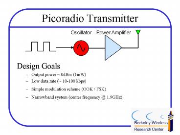
Picoradio Transmitter
- Design Goals
- Output power 0dBm (1mW)
- Low data rate ( 10-100 kbps)
- Simple modulation scheme (OOK / FSK)
- Narrowband system (center frequency _at_ 1.9GHz)
2
Schematic
Vdd 1.2V 50? Antenna
Y. H. Chee B. Otis
Oscillator
Power Amplifier
3
Design Issues
- High efficiency power amplifier
- Maximize voltage swing drain of cascode
transistor - Minimize loss by using capacitive transformer
instead of LC matching network or inductive
transformer - Maximize Q of inductor
- Maximize voltage swing of oscillator to reduce
conduction angle - Low power stable frequency reference
- Use of high Q MEMS (FBAR) resonator to get a
stable carrier frequency with minimal power - Fast rise time
4
Fabricated Die
TX 1
ST Microelectronics 0.13?m CMOS Technology Die
area 4mm x 4mm
TX 2
5
Testboard
Component Test Chip
Radio Test Chip
Y. H. Chee, S. Mellers
6
Output Spectrum
Low Frequency (LF) Channel 1.87791 GHz
High Frequency (HF) Channel 1.91612 GHz
7
TX Efficiency
Maximum Efficiency 16.5 (LF) 14.7 (HF)
Maximum Output Power 1.9mW
8
Performance Summary
9
Comparison with Existing Work
1 P. Choi, et. Al, An Experimental Coin-sized
Radio for Extremely Low Power WPAN (802.15.4)
Application at 2.4 GHz., IEEE ISSCC Digest of
Technical Papers, pp 92-3, Feb 2003. 2 T.
Melly, A. S. Porret, C. C Enz and E. A. Vittoz,
An Ultralow Power UHF Transceiver Integrated in
a Standard Digital CMOS Process Transmitter,
IEEE J. Solid State Circuits, vol. 36, no. 3,
Mar 2001.


