Simulations and Experimental Results - PowerPoint PPT Presentation
1 / 1
Title:
Simulations and Experimental Results
Description:
Uses an alternator having a separate set of stator windings to supply each output ... The switching frequency is much higher than the alternator electrical frequency. ... – PowerPoint PPT presentation
Number of Views:45
Avg rating:3.0/5.0
Title: Simulations and Experimental Results
1
Design of Dual-Output Alternators with
Switched-Mode Rectification
LEES
Gimba Hassan David J. Perreault Thomas A.
Keim Massachusetts Institute of Technology,
Laboratory for Electromagnetic and Electronic
Systems
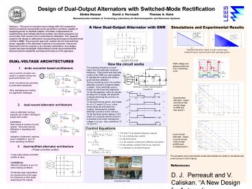
Simulations and Experimental Results
- A New Dual-Output Alternator with SMR
Abstract ---The push to introduce dual-voltage
(42V/14V) automotive electrical systems
necessitates power generation solutions capable
of supplying power to multiple outputs. A number
of approaches for implementing dual-voltage
electrical systems have been proposed, but most
suffer from severe cost or performance
limitations. This research explores the design of
alternators incorporating dual-output
switched-mode rectifiers (SMR). The proposed
approach enables the full load-matched power
capability of the alternator machine to be
achieved, with power delivered to the two outputs
in any desired combination. A prototype system
has been developed. Experimental results are
presented that demonstrate the feasibility and
high performance of the approach.
Simulated alternator output over the control
range (hatched regions represent achievable
operating points)
Alternator with SMR.
- DUAL-VOLTAGE ARCHITECTURES
How the circuit works
SMR voltage and gating waveforms over a switching
cycle
1. dc/dc converter-based
architecture
- The switching frequency is much higher than the
alternator electrical frequency. Field control
and duty ratio control of the SMR are used
together to regulate the outputs and achieve good
machine utilization. - During a switching cycle, the rectified
alternator current ix is approximately constant.
Each switching cycle is broken up into three time
segments - In the first segment, which we denote as being
hrT in length, the diode D3 conducts delivering
the current ix to the 42V bus. - In the second time period, which lasts for
h(1-r)T, switch Q2 is on. In this period diode D2
and switch Q2 conduct, delivering the rectified
alternator current ix to the 14V bus. - In the final time period, lasting (1-h)T, switch
Q1 conducts and the current ix is shunted to the
return bringing the voltage vx to zero. (See
waveforms A D and E)
- Use of a dc/dc converter can result in a system
having very good performance, but - dc/dc converters are expensive by automotive
standards - Size, packaging and cooling are significant
challenges
Alternative rectifier implementation (Simplified)
Experimental alternator output currents across
control range at 1800 rpm (idle speed )
2. dual-wound alternator architecture
- Uses an alternator having a separate set of
stator windings to supply each output - Limitations
- field control is common to both outputs. This
poses serious difficulties in regulating both
outputs - utilization of alternator machine power
capability is poor for some operating conditions
Experimental alternator output currents across
control range at 6000 rpm (cruising speed )
- dual-rectified alternator architecture
- (Phase-controlled rectifier)
- A dual-output phase-controlled rectifier is used
- Limitations
- Machine utilization is poor for some loading
conditions - Extremely large output filters are required due
to the large, low frequency current ripple
appearing at the outputs
The simulation and experimental results
demonstrate the ability to simultaneously control
power to both outputs
References D. J. Perreault and V. Caliskan.
A New Design for Automotive Alternators, 2000
International Congress on Transportation
Electronics. (Convergence 2000), pp 583 594,
October 2000, SAE paper 2000 01 C084. G.
Hassan, D. J. Perreault, and T.A. Keim. Design
of Dual-Output Alternators with Switched- Mode
Rectification, 2003 IEEE Power Electronics
Specialists Conference, June 2003.
Experimental setup


