
ST' LOUIS MERCHANTS BRIDGE DECK TRUSS REPLACEMENT - PowerPoint PPT Presentation
1 / 38
Title:
ST' LOUIS MERCHANTS BRIDGE DECK TRUSS REPLACEMENT
Description:
Owned and Operated by the Terminal Railroad Association of St. Louis ... Underground water, fiber-optic, gas and electric. Underlying BNSF tracks. Flood Wall ... – PowerPoint PPT presentation
Number of Views:216
Avg rating:3.0/5.0
Title: ST' LOUIS MERCHANTS BRIDGE DECK TRUSS REPLACEMENT
1
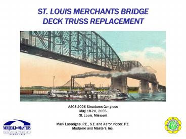
ST. LOUIS MERCHANTS BRIDGEDECK TRUSS REPLACEMENT
ASCE 2006 Structures Congress May 18-20, 2006 St.
Louis, Missouri Mark Lasseigne, P.E., S.E. and
Aaron Kober, P.E. Modjeski and Masters, Inc.
2
HISTORY BACKGROUND
- Located North of Downtown St. Louis
- Designed by George Morison and E. L. Corthell
- Built by Union Bridge Company of New York
- Completed in 1890
- Owned and Operated by the Terminal Railroad
Association of St. Louis - Services 35 Trains Daily for Local and
Transcontinental Railroad Traffic
3
ORIGINAL CONSTRUCTION
4
ORIGINAL CONSTRUCTION
5
EXISTING STRUCTURE
- Main Truss Spans Three 518-foot Pennsylvania
Trusses, supported atop granite and limestone
piers - Deck Truss Spans Three 125-foot spans at each
approach, supported atop steel towers with timber
pile-supported cylinder piers - Deck Girder Approach Spans Built-up deck girder
spans, supported atop steel towers with timber
pile-supported concrete pedestals
6
STRUCTURAL EVALUATION (1999)
- Evaluation
- Comprehensive Inspection
- Structural Rating
- Fatigue Study
- Seismic Evaluation
- Recommendations
- Increase Frequency of Deck Truss Inspections
- Near-Immediate Replacement of Deck Truss Spans
7
STRUCTURAL EVALUATION (1999)
- Evaluation
- Comprehensive Inspection
- Structural Rating
- Fatigue Study
- Seismic Evaluation
- Recommendations
- Increase Frequency of Deck Truss Inspections
- Near-Immediate Replacement of Deck Truss Spans
8
INSPECTION FINDINGS
- Deterioration
- Pin Wear
- Member Fracture
- Cracking
- Crushed Bearings
- Truss Movement
9
INSPECTION FINDINGS
- Fracture
10
INSPECTION FINDINGS
- Cracks
11
INSPECTION FINDINGS
- Pin Wear
12
INSPECTION FINDINGS
- Bearing Locations
13
INSPECTION FINDINGS
- Deterioration
14
INSPECTION FINDINGS
- Crushing
15
INSPECTION FINDINGS
- Movement
16
STRUCTURAL EVALUATION (1999)
- Evaluation
- Comprehensive Inspection
- Structural Rating
- Fatigue Study
- Seismic Evaluation
- Recommendations
- Increase Frequency of Inspections
- Near-Immediate Replacement of Deck Truss Spans
17
DECK TRUSS CONCERNS
- Structural Reliability
- Loads vs. Capacity
- Design capacity is E40
- Current traffic is comparable to E72 live load
- Main members are typically adequate to carry E72
loads - Current design standard is E80
- Condition and Stability
- Truss distortion, pin wear and section loss are a
concern - Many column caps have crushed or otherwise failed
- Pumping and deterioration is significant
18
DECK TRUSS CONCERNS
- Remaining Serviceable Life
- Fatigue Life
- Potential for cracking in fatigue-prone members
is increased - Floor system has exhausted its remaining safe
life - Main diagonals are approaching the end of their
safe life - Economic Life
- Spans inspected for problems every six months
- Significant number of repairs have already
occurred - Some repairs are temporary fixes
- Internal, operational and intangible cost of
maintaining the spans is significant
19
DESIGN RESTRICTIONS
- Rail Traffic Restrictions
- Minimal disruption to traffic required
- Two ten-day track outages allowed for
demolition/construction (staged replacement) - One track must remain in service at all times
- Much of the structure will have to be built with
the existing spans in place - Existing structure limits overhead clearance
20
DESIGN RESTRICTIONS
- Obstruction and Utility Restrictions
- Abandoned underground brick sewer
- 108 working underground sewer
- High voltage overhead power lines
- Underground water, fiber-optic, gas and electric
- Underlying BNSF tracks
- Flood Wall
- Bike Trail
- On-Structure Utilities
21
DESIGN CONSIDERATIONS
- Live Load
- Existing structure was designed for Cooper E40
- New structure to be designed for Cooper E80
- AREMA Longitudinal Force (2003)
- Load is significantly increased from previous
guideline - Forces must be applied simultaneously to both
tracks - Geometric restrictions create design limitations
(fit) - Adjustment to longitudinal forces was required
22
DESIGN CONSIDERATIONS
- Fit (West Approach, Before Bent Construction)
23
DESIGN CONSIDERATIONS
- Fit (West Approach, After Bent Construction)
24
FOUNDATION DESIGN ADJUSTMENTS
- Original Design
- 36 diameter drilled shafts
- Founded at bedrock
- 36 rock socket
- Complications
- Low overhead clearance
- Lengthy installation process
- River level complications
- Flow of liquefied material into shaft excavations
- Loosened sand causing existing foundation
settlement
25
FOUNDATION DESIGN ADJUSTMENTS
- Steel Micropile Alternative
- Adequate capacity
- Cost-effective
- Quick installation
- Adaptable to low overhead clearance
26
FOUNDATION DESIGN ADJUSTMENTS
- Modified Foundations
- Drilled Shafts
- Use at Bents E1 and W1 (river locations)
- Utilize increased overhead clearance
- Guard against scour
- Micropile
- Use at remaining locations
- Increase number of piles per foundation
- Batter piles to handle longitudinal forces
- Increase length of rock sockets to five feet
- Perform load tests to twice the design load
27
CONSTRUCTION SEQUENCE
- Center Truss Key to Staged Construction
Section at Mid-Span
Section at Tower
28
CONSTRUCTION SEQUENCE
- STEP 1 - Foundations
29
CONSTRUCTION SEQUENCE
- STEP 2 - Footings
30
CONSTRUCTION SEQUENCE
- STEP 3 Bent Walls
31
CONSTRUCTION SEQUENCE
- STEP 4 Shaft Extensions
32
CONSTRUCTION SEQUENCE
- STEP 5 Bent Caps
33
CONSTRUCTION SEQUENCE
- STEP 6 North Truss Removal
34
CONSTRUCTION SEQUENCE
- STEP 7 Deck Girder Spans
35
CONSTRUCTION SEQUENCE
- STEP 8 Remaining Truss Removal
36
CONSTRUCTION SEQUENCE
- STEP 9 Deck Girder Spans
37
CONSTRUCTION SEQUENCE
- COMPLETED STRUCTURE
38
QUESTIONS?
Recommended
CrystalGraphics Presentations


