IO Ports Review - PowerPoint PPT Presentation
1 / 13
Title:
IO Ports Review
Description:
Polled (input) Continuously read a port until desired value read ... Poll or use interrupts. HC11 App reads PORTCL to get data. STRB tells device. ... – PowerPoint PPT presentation
Number of Views:73
Avg rating:3.0/5.0
Title: IO Ports Review
1
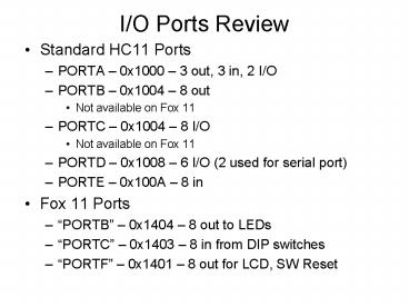
I/O Ports Review
- Standard HC11 Ports
- PORTA 0x1000 3 out, 3 in, 2 I/O
- PORTB 0x1004 8 out
- Not available on Fox 11
- PORTC 0x1004 8 I/O
- Not available on Fox 11
- PORTD 0x1008 6 I/O (2 used for serial port)
- PORTE 0x100A 8 in
- Fox 11 Ports
- PORTB 0x1404 8 out to LEDs
- PORTC 0x1403 8 in from DIP switches
- PORTF 0x1401 8 out for LCD, SW Reset
2
Using I/O Ports
- Dedicated input and output pins are generally
ready to use at reset - Configurable pins (I/O) are generally set to
input at reset, and must be configured for output
by writing (a 1) to the corresponding data
direction register - DDRC 0x1007
- DDRD 0x1009
- DDRA7 bit 7 of 0x1026
- DDRA3 bit 3 of 0x1026
- Different ports support various other peripherals
which are configured via various other registers. - When port pins are configured for alternate
functions, corresponding bit in port control
register generally has no effect. - Reference Manual is best resource.
3
A Note on HC11 Modes
- Why are ports B and C not available on Fox11?
- HC11 can operate in different modes
- Determined at reset
- Reads MODA and MODB pins at reset
- Status latched so a running program can detect
mode
4
Modes
- Single Chip Mode
- All ports available as published
- No external address or data busses
- No external memory or memory mapped I/O available
- Expanded Mode
- Ports B and C used for external address and data
bus - WaUWaT (Whats Up With That)
- Port B is 8 bits out, Port C is 8 I/O
5
PC0 PC1 PC2 PC3 PC4 PC5 PC6 PC7 PB0 PB1 PB2 P
B3 PB4 PB5 PB6 PB7
6
I/O Techniques
- Weve used a couple of techniques
- Asynchronous
- Write and read memory/ports at will/convenience
- Works well for output (LED, LCD)
- Works for some inputs (static DIP Switches)
- Polled (input)
- Continuously read a port until desired value read
- Example reading key from keypad
- Works for input.but
- Keeps processor busy
- Not efficient for many applications
7
I/O with Handshaking
- Handshaking Additional I/O lines are connected
between sender and receiver to regulate flow of
data. - Simple strobed I/O
- Sender tells the receiver that data is coming
- Full Handshaking
- Receiver tells sender that it is able to accept
data - Sender sends data
- Receiver tells sender that data was received (or
not) - HC11 offers some built-in handshaking
functionality.
8
Simple Strobed Input
- Note Applies to Single Chip Mode
- Input on PORTCL (latched register for Port C
inputs) - Set PIOC (0x1002) bit 4 (HINDS handshaking
mode) to 0 - Set PIOC bit 1 to indicate rising (1) or falling
(0) edge trigger - STRA input used to indicate when input data is
available - Read via STAF bit 7 of PIOC
- If bit 6 of PIOC is set, STAF will cause
interrupt (more on this later)
9
Simple Strobed Output
- Output on PORTB
- Set PIOC (0X1002) bit 4 to 0 (same as input)
- STRB output pin active for 2 clocks when data
written to Port B - Bit 0 of PIOC indicates polarity of STRB (active
high or low)
10
Timing Simple Strobe
11
Full Handshake Mode
- Used when both sender and receiver must agree on
when data is sent - PORTCL for data (1 to 8 bits)
- STRA input to HC11
- STRB output from HC11
12
Full Handshake Input
- STRB tells device HC11 is ready for data
- Device puts data on port
- Device pulls STRA high (or low) to signal data is
there - HC11 sees STAF bit set in PIOC
- Poll or use interrupts
- HC11 App reads PORTCL to get data.
- STRB tells device..
13
Full Handshake Output
- STRB tells device data is ready, and is set by
writing to PORTCL - Device pulls STRA high (or low) when data has
been accepted - Check STAF bit in PIOC


