
Electronics - PowerPoint PPT Presentation
1 / 14
Title: Electronics
1
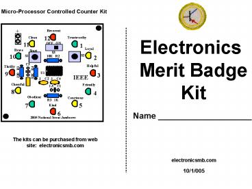
Micro-Processor Controlled Counter Kit
Electronics Merit Badge Kit
Name ____________________
The kits can be purchased from web site
electronicsmb.com
electronicsmb.com
10/1/005
2
Mode
Start
26
1
3
Micro-Processor Controlled Counter Kit
Soldering
Micro Processor The Microprocessor is programmed
to operate a sequence of commands that drives the
LEDs in different patterns The code has many
modes. Mode 1. LEDs start running fast in a
circle slowing down to a stop. Turn S3 on
press S1 Start Mode 2. LEDs start fast and
randomly blink then slowing down to a stop. Turn
S3 On, after first LED comes on press S2 Mode
button, then press S1 Start. Mode 3. LEDs
start running fast in a circle then stop after
about 30 seconds. Turn S3 On, after first LED
comes on press S2 Mode button two times, then
press S1 Start. Mode 4. LEDs start fast and
randomly blink then stop after 30 seconds. Turn
S3 On, after first LED comes on press S2 Mode
button three times, then press S1 Start. In Mode
1 and 2, if the start button is pressed a second
time while running it freezes the speed rate
until the button is pressed again to allow it to
slow to a stop. Always turn off the unit when not
using.
Safety Note A Soldering Iron gets hotter than
300 F. Do not touch the soldering irons metal
parts or you will receive a third degree burn.
A good solder joint depends on the following
1) Solder iron must have a clean, well-tinned
tip. 2) Parts to be soldered must be clean. 3)
There must be a sound mechanical joint. 4)
Parts to be soldered must be well heated before
applying solder. 5) Wait approx. 5 seconds
after soldering to allow strong mechanical
joint to form. 6) Wear safety glasses when
soldering.
25
2
4
Soldering
Micro-Processor Controlled Counter Kit
Iron
Iron
Wire
Wire
Screws
PC Board
PC Board
Solder melts at 310 F. So the wire and PC
board must be the same temperature for the
solder to melt on both items. Place soldering
iron so that it touches both the PC board and
wire. The heat from the soldering iron will
transfer to the PC board and wire at the same
time.
Wrong way
Right way
Wire
Iron
PC Board
Foam
Box
1) Place Battery in bottom of box 2) Place foam
on top of battery 3) Place PC board and push foam
into box. 4) Use two screws on opposite corners.
3
24
5
Micro-Processor Controlled Counter Kit
Soldering
When the PC board and wire are hot enough the
solder will flow and create a cone shape. If
the board is not hot enough the solder will be
rounded on the board creating somewhat of a ball.
The finishing solder should also be shiny.
After soldering, cut extra wire close to board
level.
Solder
Wrong way
Red
Wire
Iron
Black
After 3 seconds place the solder on the tip of
the iron, the wire and the PC board
all together. The solder should flow to
everything making a good connection
PC Board
1) The battery wires will be soldered to pads. 2)
Heat up battery pads and melt a lot of solder on
pad. 3) While pad is hot place wire to be
soldered onto pad. The solder will flow to
lead. 4) Connect the battery and turn on unit. 5)
If unit does not work have instructor review for
errors.
Wire
Right way
PC Board
23
4
6
Un-Soldering
Micro-Processor Controlled Counter Kit
1) Unsolder two parts from the PC board. 2)
Use pliers to hold the component next to the lead
to be unsoldered. If the lead is held with
the pliers it will draw heat from the lead. 3)
Apply soldering iron tip to PC board and wire 4)
Either use solder wick or solder sucker to draw
solder off the board. Or simply pull wire
from PC board when hot. 5) The soldering
Iron will damage electronic components if
left on device for greater than 15 seconds. So
work quickly. Sometimes it helps to put
more solder on the solder joint to improve
the thermal conductivity. 6) Clean soldering
iron tip and keep it shiny.
4) Place Switches S1, S2 and S3 in their
appropriate positions and solder.
5
22
7
Un-Soldering
With pliers, hold device close to lead that is
to be unsoldered. As heat is applied from
soldering iron, pull with pliers. With one side
out, do the same on other side.
Turn Soldering Irons on. Put safety glasses
on Proceed to Unsolder two components.
C3 22uf
C2 C4 .1uf
3) Place capacitors C3 22 uf C2 C4
.1uf
21
6
8
Micro-Processor Controlled Counter Project
Micro-Processor Controlled Counter Kit
Assembly Sequence
Brown, black, orange
R2 10K
- Place all LEDs in board, bend leads out and
solder, - then cut leads.
- Place Resistors in board, bend leads out and
solder, - then cut leads.
- 3) Place Capacitors in board, bend leads out
and solder. - Place Switch S1, S2 S3 in board and solder.
- Any orientation.
- Place Red and Black Battery wire on back of board
- and solder.
- 6) Place Battery in box with foam and cover with
PC board - 7) Use two screws to secure the PC board to box.
orange, orange, orange
R4 33K
Red, Black, Brown
R1 200
2) Place Resistors R1 200, (red, black, brown)
R2 10K, (brown, black, orange) R3 1K, (brown,
black, red) R4 33K, (orange, orange, orange)
Brown, black , red
R3 1K
7
20
9
Micro-Processor Controlled Counter Project
Soldering Kit
- Place components into PC board in the order
recommended on instruction sheet - 2) When components are placed into PC board, bend
leads out slightly to keep parts from falling
out, when the PC board is turned over for
soldering. - 3) Follow instructions as to proper orientation
of components.
LED Note Flat Edge
Shorter Lead
Cut when soldered
PC Board
Wrong
Clip wire at board
No Space, LED against board
Correct
LED Note Flat Edge
1) Place LEDs on PC board, flat side of
LEDs facing right, bend leads out, then
solder leads. After soldering cut leads
close to board.
When soldering LEDs, do not leave the solder
iron on pads for more than 5 seconds, or you will
destroy the pad.
19
8
10
Completed Kit
Kit parts PC board, 4 resistors R1200,
R210K, R3 1K, R433K, 3 Capacitors C2 .1uf,
C3 22uf, C4 .1uf C1 not needed 12 LEDs 3
different colors, Red, Yellow, Green, 1 slide
switch S3, 2 push button S1 S2, one battery
holder and one box
9
18
11
PC Board
Micro-Processor Controlled Counter Project
Reverent
Reverent
12
Trustworthy
Clean
12
Trustworthy
Clean
11
1
OFF ON
11
OFF ON
S3
1
Loyal
Brave
Start
Loyal
2
10K R2
10
S1
Brave
Start
S3
10
Thrifty
S2
S2
S1
Helpful
2
10K R2
U1
9
3
33K R4
220 R1
IEEE
C3
Helpful
Thrifty
Cheerful
Friendly
C4.1
C2 .1
C3
8
4
220 R1
9
33K R4
U1
3
Courteous
Obedient
IEEE
R3 1K
5
.1 C4
.1 C2
7
Kind
6
Cheerful
Friendly
1.5 C1
2005 National Scout Jamboree
8
4
Kit contains a microprocessor that is programmed
to drive 12 LEDs The micro is programmed to
starts blinking lights fast, then slowly comes
to a stop. You will draw the circuit schematic
this class, then next class build the kit.
Obedient
Courteous
R3 1K
5
7
Kind
6
2005 National Scout Jamboree
17
10
12
Micro-Processor Controlled Counter
LEDs
Micro Processor PIC 16F818
Dot means a connection
1
4.5 VDC
2
3
C3 22uf
A1 A2 A3 A4 A7 B1 B2 B3 B4 B5 B6 B7
C4 .1 uf
SW1 n.o.
R3 1 K
4
SW3 Power
5
R2 10 K
VDC MR RA0 RB0 GND
6
Start
7
4.5 Volt Power
8
SW2 n.o.
C2 .1 uf
9
R4 33K
10
11
12
Mode
R1 200
Ground
11
16
13
Micro Processor The Microprocessor is programmed
to operate a sequence of commands that drives the
LEDs in different patterns The code has many
modes. Mode 1. LEDs start running fast in a
circle slowing down to a stop. Mode 2. LEDs
start fast and randomly blink then slowing down
to a stop. Mode 3. LEDs start running fast in a
circle then stop after about 30 seconds. Mode
4. LEDs start fast and randomly blink then stop
after 30 seconds. In Mode 1 and 2, if the start
button is pressed a second time while running it
freezes the speed rate until the button is
pressed again.
After SW3 is closed, voltage flows to the
circuit. The micro is programmed to count in
binary from 1 to 12. When SW1 is pressed,
capacitor C3 is discharged. Then when the
button is released the capacitor begins to
charge as shown below. As the capacitor is
charged the voltage goes toward 0 volts. This
causes the LEDs to blink from a fast rate to a
slow rate then stop. By pressing SW2, changes
the mode so the LEDs blink randomly.
4.5 VDC
SW3 Closed
SW1 Pressed
SW1 Pressed again
15
12
14
Micro-Processor Controlled Draw the Schematic /
Counter Circuit Connect the lines
LEDs
Dot means a connection
Micro Processor PIC 16F818
1
4.5 VDC
2
C4 .1 uf
3
R2 10 K
SW1 n.o.
R3 1 K
4
A1 A2 A3 A4 A7 B1 B2 B3 B4 B5 B6 B7
C3 22uf
5
VDC MR RA0 RB0 GND
SW3 Power
6
7
4.5 Volt Power
8
SW2 n.o.
C2 .1 uf
9
R4 33K
10
11
12
R1 200
Ground
13
14
Recommended
CrystalGraphics Presentations


