IH structure - PowerPoint PPT Presentation
IH structure
Inside the resonator tank cylindrical cavity drift tubes of varying length ... The second acceleration stage, the IH-structure accelerates the ions from 0.3 ... – PowerPoint PPT presentation
Title: IH structure
1
IH-structure
The second acceleration stage, the IH-structure
accelerates the ions from 0.3 MeV/u to an
extraction energy between 1.1 and 1.2 MeV/u. The
variation of the final energy of the IH-structure
can be achieved by adjusting the gap voltage
distribution via capacitive plungers.
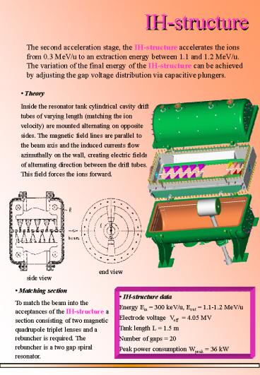
- Theory
- Inside the resonator tank cylindrical cavity
drift tubes of varying length (matching the ion
velocity) are mounted alternating on opposite
sides. The magnetic field lines are parallel to
the beam axis and the induced currents flow
azimuthally on the wall, creating electric fields
of alternating direction between the drift tubes.
This field forces the ions forward.
end view
side view
- Matching section
- To match the beam into the acceptances of the
IH-structure a section consisting of two magnetic
quadrupole triplet lenses and a rebuncher is
required. The rebuncher is a two gap spiral
resonator.
- IH-structure data
- Energy Ein 300 keV/u, Eout 1.1-1.2 MeV/u
- Electrode voltage Veff 4.05 MV
- Tank length L 1.5 m
- Number of gaps 20
- Peak power consumption Wpeak 36 kW
PowerShow.com is a leading presentation sharing website. It has millions of presentations already uploaded and available with 1,000s more being uploaded by its users every day. Whatever your area of interest, here you’ll be able to find and view presentations you’ll love and possibly download. And, best of all, it is completely free and easy to use.
You might even have a presentation you’d like to share with others. If so, just upload it to PowerShow.com. We’ll convert it to an HTML5 slideshow that includes all the media types you’ve already added: audio, video, music, pictures, animations and transition effects. Then you can share it with your target audience as well as PowerShow.com’s millions of monthly visitors. And, again, it’s all free.
About the Developers
PowerShow.com is brought to you by CrystalGraphics, the award-winning developer and market-leading publisher of rich-media enhancement products for presentations. Our product offerings include millions of PowerPoint templates, diagrams, animated 3D characters and more.


