Analog to Digital Converters ADCs - PowerPoint PPT Presentation
1 / 11
Title:
Analog to Digital Converters ADCs
Description:
Analog signals are converted to digital form by a ADC in a two step process: Step 1: Analog signal is sampled (i.e. measured) at periodic points in time. ... – PowerPoint PPT presentation
Number of Views:198
Avg rating:3.0/5.0
Title: Analog to Digital Converters ADCs
1
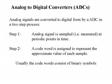
Analog to Digital Converters (ADCs)
Analog signals are converted to digital form by a
ADC in a two step process Step 1 Analog signal
is sampled (i.e. measured) at periodic points
in time. Step 2 A code word is assigned to
represent the approximate value of each
sample. Usually the code words consist of binary
symbols
2
Sample at T intervals
1 0 1
1 1 0
Each sample is represented by a three-bit code
word corresponding to the amplitude zone into
which the sample falls
3
Since each sample value is converted into a code
word, it can be represented by a digital waveform
1 0 1
1 1 0
4
Q Convert the following Analog waveform into its
resulting Digital waveform.
5
Signal Sampling Sampling Frequency ( fs )
The rate of fS at which a signal must be
sampled depends on the frequencies of the signal
components (All real signals can be considered to
consist of sinusoidal components having various
frequencies, amplitudes, and phase) If the
signal contains no components with frequencies
higher than fH (highest frequency) The signal
can (in theory) be exactly reconstructed from
its samples, provided that the the sampling
frequency fS is selected to be twice fH fS gt
2fH
6
e.g. High-fidelity audio signals have a highest
frequency of 15KHzTherefore minimum sampling
rate that sound be sued for audio signals is
30KHz.
Note Practical considerations dictate a sampling
frequency somewhat higher than the theoretical
minimum. Audio compact-disk technology coverts
audio signals to digital form with a sampling
rate of 44.1KHz
Desirable to use lowest practical sampling
rate - minimises amount of data (in the form of
code words) that must be stored or
manipulated.
The interval between samples T is the reciprocal
of the sampling rate T 1 / fS
7
Quantization Error
Another important consideration is the number of
amplitude zones to be used when converting analog
signals to digital form.
Exact signal amplitudes cant be represented,
because all amplitudes falling into a given zone
have the same code word.
Thus, when a DAC converts the code word to
recreate the original analog waveform, it only
creates an approximate to the original signal
with the reconstructed voltage in the middle of
each zone.
8
This Quantization error consists between the
original signal and the reconstruction.
Quantization error can be reduced by using a
larger number of zones, which require longer code
words.
The number of amplitude zones (N) is related to
the number of bits in the code word by N 2K
(where K number of bits)
9
e.g. if using an 8-bit ADC. How many amplitude
zones are there? 8-bits ? k 8 N 2K ?
Amplitude zones 28 256
In CD technology, 16-bit words are used to
represent the sample values ? approx 64K
amplitude zones With this number of bits, it is
very difficult a listener to detect the effects
of Quantization error in the reconstructed audio
signal.
10
Determining an ADC Specification
Q We need to digitise a signal that ranges from
1V to 1V with a resolution of at most 0.5mV.
Determine the ADC specification.
A Step 1 Calculate minimum number of zones in
the total range. Total Range -1V to 1V 2V
Resolution 0.5mV Amplitude zones (N)
2V/0.5mV 4000
Step 2 Calculate number of bits required to
provide number of Amplitude zones. N 2K ?
4000 2K. Since 212 4096, we require
K12. ANS A 12-bit ADC is required.
11
Q We need to digitise a signal that ranges from
2.5V to 2.5V with a resolution of at most
0.05mV. Determine the ADC specification.
Q We need to digitise a signal that ranges from
1V to 10V with a resolution of at most 1mV.
Determine the ADC specification.
Q We need to digitise a signal that ranges from
5V to 10V with a resolution of at most 0.75mV.
Determine the ADC specification.


