
Circuit Diagram PowerPoint PPT Presentations
All Time
Recommended

Circuit Diagrams Circuit Diagrams Circuit Diagram: a short-hand way of drawing an electric circuit using standard symbols Circuit Diagrams Circuit Diagram: a ...
| PowerPoint PPT presentation | free to view

In this presentation we have mentioned few mini electronics projects circuit diagrams, the complete information of these electronics projects can be found by clicking on the link given below of each schematic diagram.
| PowerPoint PPT presentation | free to download

Circuits with Flip-Flop = Sequential Circuit Circuit = State Diagram = State Table State Minimization Sequential Circuit Design Example: Sequence Detector
| PowerPoint PPT presentation | free to download

This document provides an introductory overview of basic circuit design principles, highlighting key electronic components such as resistors, capacitors, and transistors. It covers how electric circuits work, their fundamental elements, and illustrates a simple example of a circuit with a visual diagram to help beginners understand the essential concepts of electricity flow and component interaction. Suitable for enthusiasts and beginners in electronics, this guide serves as a stepping stone into the vast world of electronic design and engineering.
| PowerPoint PPT presentation | free to download

Classical method: 9 variable input needs 29 = 512 line of truth table ... From the truth table, decoder circuit 2x4 is ... Encoder is the inversion of decoder. ...
| PowerPoint PPT presentation | free to view

Components, Symbols, and Circuitry of Air-Conditioning Wiring Diagrams Electricity for Refrigeration, Heating and Air Conditioning 7th Edition
| PowerPoint PPT presentation | free to view

The following circuit is part of a 555 timer diagram. The power supplies have been connected already. +V 4 8 Add 2 resistors and a capacitor to make:
| PowerPoint PPT presentation | free to download

Information Theoretic Approach to Minimization of Logic Expressions, Trees, Decision Diagrams and Circuits Summary Contributions of this approach New information ...
| PowerPoint PPT presentation | free to download

Components, Symbols, and Circuitry of Air-Conditioning Wiring Diagrams Electricity for Refrigeration, Heating and Air Conditioning 7th Edition
| PowerPoint PPT presentation | free to view
In-Circuit Test Concepts Part 1 In-Circuit Test Overview Michael J Smith Michael.J.Smith@Teradyne.com Agenda What and Why In-Circuit Test? The Defect Spectrum ...
| PowerPoint PPT presentation | free to view

Automatic Test Pattern Generation for Functional RTL Circuits Using Assignment ... HITEC. Experimental Results (2) 0.01. 0.1. 1. 10. 100. 1000. 10. 100. 1000 ...
| PowerPoint PPT presentation | free to view

1 The diagram above shows a light ray approaching a mirror. ... 3 Light traveling through a pair of eyeglasses is. F refracted. G transmitted. H absorbed ...
| PowerPoint PPT presentation | free to view

Chapter 10 Diodes 1. Understand diode operation and select diodes for various applications. 2. Analyze nonlinear circuits using the graphical load-line technique.
| PowerPoint PPT presentation | free to view

... diagram to the right shows a real battery, with internal ... 2) The circuit diagram to the right shows 3 resistors connected in series to an ideal battery. ...
| PowerPoint PPT presentation | free to view

Combination Circuits Steps to Solve Combined Series-Parallel Circuits 1. If necessary, draw a diagram of the circuit. 2. Find any parallel resistors in the circuit ...
| PowerPoint PPT presentation | free to view
Circuits & Switches Circuits An Electric Circuit is an uninterrupted conducting path for an electric current. In order for electrons to flow and do work, there must ...
| PowerPoint PPT presentation | free to view

... Current and Resistance is known as Ohms Law. Schematic circuit diagram. Water flow analogy Voltage ( V ) Pressure ( V ) Resistance ( R ) Reduced flow ( R ...
| PowerPoint PPT presentation | free to download

Electrical Circuits Section 7.3 SC Standards Covered PS 6.8 Represent an electric circuit by drawing a circuit diagram that includes the symbols for a resistor ...
| PowerPoint PPT presentation | free to view

lesson 6: circuit diagrams. lesson 7: Resistance. lesson 8: Is electricity dangerous? ... To learn to make circuits by using circuit diagrams. ...
| PowerPoint PPT presentation | free to view
Find a lot of simple basic circuit diagram, components and useful electronic circuits at eleccircuit.com. Here you get some unique project idea on different electronics circuits so that you can make it easily and use it.
| PowerPoint PPT presentation | free to download

CIRCUITS In the circuit shown below: How much power is dissipated by the 12 resistor? What is the value of the potential at points a, b, c, and d?
| PowerPoint PPT presentation | free to view

Phasor Circuit Analysis Phasor Diagrams, Voltage and Current Division Phasor Diagram Phasors are denoted by vectors in 2-D space. Phasor diagrams graphically ...
| PowerPoint PPT presentation | free to download
What are the components of electric circuit? This presentation will explain about electric circuit
| PowerPoint PPT presentation | free to download
ELECTRICAL CIRCUITS ... cell battery switch lamp motor ammeter voltmeter buzzer resistor variable resistor types of circuit There are two types of electrical ...
| PowerPoint PPT presentation | free to download

Chapter 2 Resistive Circuits Chapter 2 Resistive Circuits Circuit Analysis using Series/Parallel Equivalents Begin by locating a combination of resistances that are ...
| PowerPoint PPT presentation | free to view

Ex: Car battery. Circuit Diagrams. Use symbols to represent parts of a circuit. Shows one or more complete paths that charge can flow. Current flow ...
| PowerPoint PPT presentation | free to view

Circuit Switching Jaringan Switching Untuk transmisi data yang melampaui area lokal. Simpul switching tidak berkaitan dengan isi data. Jaringan switching sederhana ...
| PowerPoint PPT presentation | free to view

Overview of the Circuit Multiplier Subtractor Comparator Multiplexer Block Diagram Functions Of Individual Parts Inputs: two, 16 unsigned bits each ( A and B ...
| PowerPoint PPT presentation | free to download
... circuit breakers, and ground-fault interrupters (GFI ... Chapter 23 : Series and ... Slide 9 Slide 10 Slide 11 Slide 12 Slide 13 Slide 14 Slide ...
| PowerPoint PPT presentation | free to download
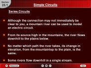
... a mountain river can be used to model an electric circuit. From its source high in the mountains, ... its change in elevation, from the mountaintop to the ...
| PowerPoint PPT presentation | free to download

11.2 Series and Parallel Circuits pp. 448 452 Circuit Diagrams Engineers and designers of electrical circuits use special symbols that show the components and ...
| PowerPoint PPT presentation | free to view

Receiver Circuit Testing. Test setup. Eye diagrams. BER measurement. Eye - BER relationship. Circuit Test Setup. Pattern Generator ...
| PowerPoint PPT presentation | free to download

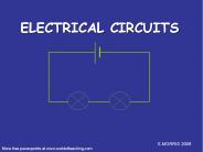
ELECTRICAL CIRCUITS All you need to be an inventor is a good imagination and a pile of junk.-Thomas Edison
| PowerPoint PPT presentation | free to download

Stick Diagrams Stick Diagrams Stick Diagrams Stick Diagrams VLSI design aims to translate circuit concepts onto silicon. stick diagrams are a means of capturing ...
| PowerPoint PPT presentation | free to download

... in an inductive load in an AC circuit can be represented by a phasor diagram: ... an Ohm's Law relationship for the combined loads in the series RCL circuit: ...
| PowerPoint PPT presentation | free to view

SERIES CIRCUITS Lesson 8 Series Circuits Some circuits provide a single pathway for electric current. A circuit that provides only one pathway for electric current is ...
| PowerPoint PPT presentation | free to download
CAPACITORS IN SERIES AND PARALLEL A circuit with CAPACITORS IN PARALLEL is shown in the diagram below. According to Kirchhoff s loop rule, ...
| PowerPoint PPT presentation | free to download
Combinational MOS Logic Circuit A. Marzuki Topics Static Characteristic Dynamic Characteristic Stick Diagram Two-Input NOR Gate VOL k = Cox W/L CMOS NOR GATE CMOS ...
| PowerPoint PPT presentation | free to download
sequential circuits definition of sequential circuit synchronous sequential circuit asynchronous sequential circuit memory elements classification: latches and flip-flops
| PowerPoint PPT presentation | free to download

Title: Electric Circuit s - 1 Author: David Rosengrant Last modified by: David Rosengrant Created Date: 2/7/2004 5:46:11 AM Document presentation format
| PowerPoint PPT presentation | free to view
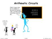
Arithmetic Circuits Didn t I learn how to do addition in the second grade? UNC courses aren t what they used to be... 01011 +00101 10000 Finally; time to build ...
| PowerPoint PPT presentation | free to download
SIMPLE ELECTRIC CIRCUITS. Lesson 72. Teacher: M. Kane. Subject: ... of a light bulb, conductors, insulators, single circuit diagrams, switches, and solutions. ...
| PowerPoint PPT presentation | free to view
Collection Circuits J. McCalley * * * * * * * * * * * * * * * * * * * * * * * * * * * * * * * * * * * * * * * * * * * * * * * * * * * * * * * * * * * * * * E. Muljadi ...
| PowerPoint PPT presentation | free to download

This fits the general sequential circuit diagram at the bottom. Combinational. circuit ... Then we can turn that table or diagram into a sequential circuit. 7/2/09 ...
| PowerPoint PPT presentation | free to view

Ideal Circuit State Transition Diagram and Example Output. Spice Display Block Diagram ... Enqueued List is 64-bit register. Stack module abstraction ...
| PowerPoint PPT presentation | free to download

Combinational Circuit Design & Layout. Sequential Circuit Design & Layout ... Example - Stick Diagrams (1/2) Circuit Diagram. Pull-Down Network (The easy part! ...
| PowerPoint PPT presentation | free to view

Title: Electric Circuit s - 1 Author: David Rosengrant Last modified by: jes hern Created Date: 2/7/2004 5:46:11 AM Document presentation format
| PowerPoint PPT presentation | free to view

Electric Circuits. Battery and a Bulb ... Electric current has but a single pathway ... Simple diagrams of electrical circuit elements are schematic diagrams ...
| PowerPoint PPT presentation | free to view

... the correct carry bit is called a half adder. Adders. Circuit diagram representing ... A circuit called a full adder takes the carry-in value into account ...
| PowerPoint PPT presentation | free to view

... is a special case of the Thevenin and Norton Theorem ... Norton's Theorem states that it is possible to simplify any linear circuit, no ... Norton form: ...
| PowerPoint PPT presentation | free to download

A Picture Diagram of a Torch British Standard Circuit Symbols A Circuit Diagram of a Torch Basic Electronic Components Exercise 1 Circuit Diagrams Exercise 2 Circuit ...
| PowerPoint PPT presentation | free to view

Here is our simple circuit again with just an emf and resistor. ... Which of these diagrams represent the same circuit? 1. a and b. 2. a and c. 3. b and c ...
| PowerPoint PPT presentation | free to view

Electricity and circuits
| PowerPoint PPT presentation | free to view

FACULTY OF EDUCATION Department of Curriculum and Pedagogy Physics Circuits Science and Mathematics Education Research Group Supported by UBC Teaching and Learning ...
| PowerPoint PPT presentation | free to download
Here you can get information about Digital Electronics Circuits and Digital numbers
| PowerPoint PPT presentation | free to download