radiometer
1 / 18
Title: radiometer
1
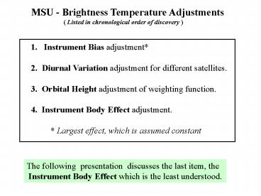
- MSU - Brightness Temperature Adjustments
- ( Listed in chronological order of
discovery ) - Instrument Bias adjustment
- 2. Diurnal Variation adjustment for different
satellites. - 3. Orbital Height adjustment of weighting
function. - 4. Instrument Body Effect adjustment.
- Largest effect, which is assumed
constant
The following presentation discusses the last
item, the Instrument Body Effect which is the
least understood.
2
Adjustment Procedures for MSU AMSU
Measurements
Adjustment
Procedure
Using A-Priori Satellite Information
Orbital Height Adjustment
X-Scan Measurements (Christy)
or Climate Model (Wentz)
Diurnal Variation Adjustment
Instrument Bias Adjustment
Using Overlapping Satellite Measurements
Instrument Body Effect Adjustment
Using Overlapping Satellite Measurements
3
Instrument Body Effect (IBE)
John Christy found that the MSU measurements
varied slightly, and diurnally, with instrument
temperature and adjusted the measurements.
IBE adjustment DTb -a T - To , a
constant, T?warm
load temperature, Tofixed reference
Possible sources of Instrument Body Effect
1. Radiometer nonlinearity
2. Antenna side lobe contributions
3. Residual diurnal temperature variation
4
Microwave Radiometer
RECEIVER SYSTEM
ANTENNA SYSTEM
Square Law
Vb
Video Amplifier
Scan
IF Amp
RF Amp
V
I
Mixer
Motor
Detector
Vw
G
m
Vc
Local
RF Radio Frequency
Oscillator
IF Intermediate Frequency
Warm Load
z
Detector Response ltVgt a2ltI2gt a4ltI4gt
where m 3 a4 KBG /a2 KBoltzmans
constant, BBandwidth, G IF-Amplifier Gain
Cold Space Radiation
Earth Radiation
Tw
Tc
Tb
5
Nonlinear Radiometer Response
V
Time-averaged voltage
Square Law
V
I
1
Detector
Output Voltage
Input Current
m
I
Nyquist theorem
KBoltzmans constant
GAmplifier gain,
BBandwidth TAmplifier temperature, TS
Radiometric temperature
2
Combining 1 and 2
3
Two-point radiometer calibration eliminates bo
and b1 from ltV gt so that
6
Nonlinear Calibration Equation
The brightness temperature viewed by the
radiometer Tb is
- where Vb is the corresponding output
voltage or counts. The first - bracketed term is the linear term it is
directly proportional to the - output voltage. The second term contains the
nonlinear parameter m - resulting from an imperfect square-law detector
m is proportional to the - amplifier gain G which is temperature dependent.
Both the slope S and - intercept I are obtained from the two-point
radiometer calibration, i.e.,
where Tc is the temperature and Vc is the
voltage for the cold space observation and Tw
and Vw are the corresponding warm target data.
7
By approximating Tb by the linear term, the
calibration equation becomes
The nonlinear term is a function of
m(Tb-Tc)(Tw-Tb) ? - D Tb. The graphs below show
the MSU - laboratory measurements of m (Left) and
the changes in both m (Dm) and D Tb (Right)
resulting from a 5K change in instrumental
temperature.
8
1. Nonlinearity Temperature Correction
The ? parameter is approximated as a linear
function of instrument temperature, T ,
-1
m mo 1 a? (T - To ) (K
)
where mo is the nonlinearity at temperature To
so that Tb becomes
Tb Tbo DTb
where
Tbo I S Vb - mo (Tb - Tc)(Tw - Tb)
and
DTb - a? mo T - To (Tb - Tc)(Tw - Tb)
Christy and Wentz use ?Tb a T- To with T
? Tw and To has fixed values between 274 and
280 K depending on the satellite.
9
2. Side Lobe Temperature Correction
A major portion of the antenna side lobes, hC ,
sees the cold-space radiation, Tc. A smaller
portion of the side lobes, hS , sees the solar
radiation, TSL , reflected with reflectivity R
from materials on the spacecraft.
The brightness temperature can also be written as
where
Earth
This adjustment is very different than that used
by Christy Wentz, i.e.,
10
Summary of Indirect Diurnal Sources of Radiation
Source Brightness
Temperature Correction Estimate
1. Detector Nonlinearity DTb -a? mo
T-To (Tb - Tc) (Tw - Tb) - 0.1 to 0.3
K
2. Antenna Side Lobes
? ?
This source contains the instrument
temperature, T.
mo nonlinearity at temperature To a
nonlinear temperature parameter Tc cold space
temperature Tw warm load
temperature T instrument temperature
Tb brightness temperature hS
fraction of solar radiation hC fraction
of cold-space radiation TSL solar radiation
temperature R spacecraft
reflectivity
Christy and Wentz refer to these corrections
as an Instrument Body Effect and express the
correction as DTb a T-To where T ? Tw .
11
Appendices
12
(No Transcript)
13
(No Transcript)
14
(No Transcript)
15
Effects of Calibration on Derived Temperature
Dependence and Trend (Wentz)
Linear Calibration (My Comment)
Used by Vinnikov
Linear calibration results in the smallest
temperature dependence
Trend is independent of calibration algorithm
What is the source of target factor in the
case of the linear calibration?
16
Nonlinear parameter as a function of instrument
temperature. Solid-Line Laboratory
Measurements Mo, T, et al., JGR-106, 10145-10150,
2001 Dashed-Line Satellite Derived (Wentz)
17
Nonlinear minus Linear TB plotted against TB
for different nonlinear parameters.
18
(No Transcript)


