Electromagnetic Sensors - PowerPoint PPT Presentation
1 / 33
Title:
Electromagnetic Sensors
Description:
Magnitude is used to find amount of charge. Polarity is found from ... found using Network Analyzer ... Field magnitude is determined from a calibrated ... – PowerPoint PPT presentation
Number of Views:2113
Avg rating:3.0/5.0
Title: Electromagnetic Sensors
1
Electromagnetic Sensors
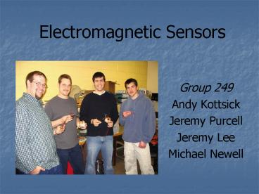
- Group 249
- Andy Kottsick
- Jeremy Purcell
- Jeremy Lee
- Michael Newell
2
Introduction
- Electromagnetic theory is difficult to apply to
real world situations. - Simple measurements often require complex
equipment and understanding for the measurement
of electromagnetic fields.
3
Project Goal
- Create a suite sensors to aid in the
measurement and understanding of the following - Electric Fields
- Magnetic Fields
- Charge
4
Requirements
- Cover four frequency ranges Static, 0 to 1 KHz,
1KHz to 100MHz, and 100MHz to 1GHz - Accurately measure the source for which the
sensor is designed - Minimal interference with surrounding electronic
devices - The sensors need to have test points for
measurements - Inexpensive
- Classroom and student usability
- Output resulting measurements to a graphical
interface
5
Sensor Choices
Field Mill - Charge
Flux-Gate DC Magnetic
Log Periodic Dipole Array Magnetic and Electric
(.6-2.4 GHz)
Loop Coils Magnetic and Electric (1-200 MHz)
6
Options Charge Measurement
- Field Mill
- J-FET Transistor
- Charged Plates
7
Field Mill Sensor
- Measures charge
- Amount of charge determined in Coulombs
- Polarity of charge determined as positive or
negative
- Commonly used to measure charge in clouds and
the detection of lightning
8
Field Mill Theory
- Rotating vane creates a sinusoidal output
- Magnitude is used to find amount of charge
- Polarity is found from phase information
Case 1
Case 2
i
i
R
R
Block Plate
Block Plate
e -
- - - - - - - -
- - - - - - - -
-
-
e-
Vout
Vout
9
Field Mill Calibration
10
Final Field Mill
11
Options - Static Magnetic Field
- Giant Magnetoresistive
- SQUID
- Fluxgate
12
Flux-Gate Sensor
- Measurement of static magnetic fields
- Field intensity determined in Gauss
- Ferromagnetic core driven in saturation
- Commonly used for the measurement of the earths
magnetic field
13
Theory of flux gate
Flux -
Magnetic field
No
Flux net
Net Flux has a value when external field is
present
Flux
Vo
14
Flux-gate calibration
15
Final Flux-Gate
16
High Frequency Electric/Magnetic Field
consideration
- Half wave dipole
- Log Periodic Dipole Array
- PCB patch antenna
- Loop Coil
17
Magnetic Loop Sensors
- Magnetic and electric fields from 1MHz to 200MHz
- Field magnitude can be determined from
calibrated Antenna Factor
18
Loop Antenna Theory
- Equivalent circuit found using Network Analyzer
- Capacitance or inductance added to shift the
resonant frequency where max power is received
19
Antenna Factor (AF) Theory
- Used for loop coil and periodic dipole
calibrations - AF Einc / Vreceived
- Einc ?oHinc where ?o 377?
- ?o is the intrinsic impedance of free space
20
Calibration of Loop Coil
Reading from Calibrated Antenna
Electric/Magnetic Field
AF for Loop Coil
Source Signal
Reading from Loop Coil
Experimental Setup
21
Loop Antenna Calibration
22
Final Calibrated Loops
1-30 MHz
40 200 MHz
23
High Frequency Electric/Magnetic Field
consideration
- Half wave dipole
- Log Periodic Dipole Array
- PCB patch antenna
- Loop Coil
24
Log Periodic Dipole
- Measure magnetic and electric fields from 600MHz
to 2.4GHz - Field magnitude is determined from a calibrated
Antenna Factor
- Commonly used for broadband UHF and VHF
applications
- Low VSWR over operating range minimizes
reflections
25
(No Transcript)
26
Dipole Calibration
27
Final Dipole
28
Budget
Discrete (R,L,C, Diodes etec) 65.96
IC's PIC's, 555 timers, etc 29.74
Hardware(Motors, PCB's, LCD's) 136.50
Power Supplies 55.89
Enclosure(BNC, Headers, Cables, Wires) 155.61
Total 443.70
29
Future Work
- Field Mill
- Miniaturize
- Distributed Sensor Network
- Adjustable Gain
- Relate Charge to Electric Field
- Remove Distance Dependency
- Flux-Gate
- Wider Calibration Bandwidth
- Adjustable Gain
- Calibration Below Earths Field
- Add 2 more dimensions
- Low Power Design
- Loop Coil
- Downshift and Sample
- Use FFT Calculation
- Better Variable Caps
- Increase Sensitivity
- Try to reduce capacitance
- Log Period Dipole
- More rugged antenna
- Antenna stand
- Obtain more accurate simulation
- Study which end to put the load
- Experiment with wire sizes
30
Problems Encountered
- Best sensors to measure each range
- Interfacing the sensors
- Impedance matching issues
- Power sources
Lessons Learned
- Start early
- Finalize the requirements early
- Be prepared to make changes, nothing is
concrete - Know the software is working or being handled
correctly - Target the harder problems sooner rather than
later - Test all circuits before building any boards
31
Summary
Coverage Range of Devices Coverage Range of Devices Coverage Range of Devices Coverage Range of Devices Coverage Range of Devices Coverage Range of Devices Coverage Range of Devices
Device Static Charge DC Magnetic Field 1-200 MHz Magnetic Field 1-200 MHz Electric Field 600-1800 MHz Electric 600-1800 MHz Magnetic
Field Mill
Fluxgate
Loop Coil
Log Periodic
32
- Questions?
33
Antenna Equations
Vreceived(dBuV) Vreceived(dBm) 107


