MODULE TYPE TAA - PowerPoint PPT Presentation
1 / 13
Title:
MODULE TYPE TAA
Description:
By means of the signal Zn 1, the pilot valve is reset by the following stepper ... construction of the OR gate. X : input (from signalling element) ... – PowerPoint PPT presentation
Number of Views:494
Avg rating:3.0/5.0
Title: MODULE TYPE TAA
1
- MODULE TYPE TAA
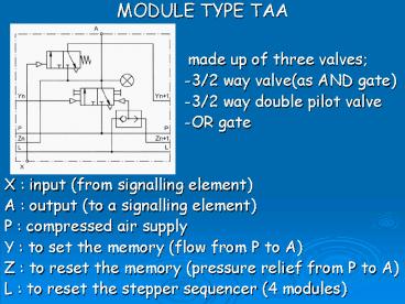
- made up of three valves
- -3/2 way valve(as AND gate)
- -3/2 way double pilot valve
- -OR gate
- X input (from signalling element)
- A output (to a signalling element)
- P compressed air supply
- Y to set the memory (flow from P to A)
- Z to reset the memory (pressure relief from P
to A) - L to reset the stepper sequencer (4 modules)
2
- MODE OF OPERATION OF MODULE TAA
- The memory is set by a signal from the preceding
module. This causes a signal to be sent to A,
which activates the final control element and
thus actuator. - The actuator signals via a sensor (signal
element) at input X that a step has been
completed. - The signal at input X reverses the AND gate,
which sets the memory of the following module via
Yn1 (pressure is supplied to the AND gate via P)
3
- MODE OF OPERATION OF MODULE TAA (cont.)
- Simultaneously to the signal at A, which comes
from the memory, this signal is passed back via
Zn and the OR gate to the previous memory and
resets it. - The OR gate enables the sequencer to resume the
initial position (signals at output A and Yn1)
in any situation (e.g. emergency stop)
4
- STEPPER MODULE, EXTENSION
- four TAA stepper modules
5
- STEPPER MODULE, EXTENSION
- TAA TAA TAA TAA
- P Supply port Yn1 Set output
- A1, A2, A3, A4 Outputs Y Set input
- X1, X2, X3, X4 Acknowledgements Zn Reset
Output - L Reset (clear) Zn1 Reset Input
6
- STEPPER MODULE, EXTENSION (cont.)
- Consists of a memory (3/2-way double pilot valve)
plus an AND and OR gate, and incorporates a
visual switching indicator and manual override. - The double pilot valve, with air applied at P, is
actuated, i.e. reversed, via inlet Y. - Produces a signal at outlet A for the intended
switching step, this signal also resets a
previous step, actuates the visual indicator and
is applied to the AND gate.
7
- STEPPER MODULE, EXTENSION (cont.)
- As soon as an acknowledgement signal of the
initiated switching operation has been received
at X, flow is opened at the AND gate and the
following stepper module actuated via Yn1. - An OR gate has been connected in series to port Z
of the double pilot valve. By means of the signal
Zn1, the pilot valve is reset by the following
stepper module, i.e. the memory is cleared. - The second inlet L can be used to return the
entire sequencer to its starting position (e.g.
for reset following an EMERGENCY-STOP).
8
- MODULE TYPE TAB
- -similar to module TAA
- -the difference is in the
- construction of the OR gate
- X input (from signalling element)
- A output (to a signalling element)
- P compressed air supply
- Y to set the memory (flow from P to A)
- Z to reset the memory (pressure relief from P
to A) - L to reset the stepper sequencer (4 modules)
9
- MODE OF OPERATION OF MODULE TAB
- There must always be flow to A in the previous
memory in the initial position and it must be set
so that via the AND gate of this module and Yn1
a continuous pulse for renewed setting of the
first memory is present at the AND gate switched
ahead of the sequencer. - If, together with the start pulse, the first
memory is via the AND gate, then the previous
memory is reset via Zn1, i.e it is ready to take
over the final step of the new operating cycle.
10
- STEPPER MODULE
- three TAA stepper modules
- one TAB stepper module
11
- STEPPER MODULE, EXTENSION
- TAA TAA TAA TAB
- P Supply port Yn1 Set output
- A1, A2, A3, A4 Outputs Y Set input
- X1, X2, X3, X4 Acknowledgements Zn Reset
Output - L Reset (clear) Zn1 Reset Input
12
- STEPPER MODULE (cont.)
- In the case of module type TAB, an OR gate is
positioned upstream of the Yn inlet of the double
pilot valve. - If a signal is applied at Yn or L, the valve is
reversed and a signal appears at outlet A, this
signal also resets the preceding stepper module,
the visual indicator and the AND gate is supplied
with pressure. - When the acknowledgement signal reaches X, the
AND flow is released and the signal Yn1 appears,
also maintained if the entire sequencer is reset
at L and can thus be used for a renewed start.
13
- STEPPER MODULE (cont.)
- When the sequencer chain is started, the module
is reset externally at port Z via the reset
signal Zn1 of the first module of the sequencer.
- With the TAA modules, an OR gate is connected
upstream of port Z in the double pilot valve. - This is why, in this case, the double pilot valve
is returned via a signal at Zn1 from the
following stepper.

