Dispersion model the dispersed plug flow model
1 / 39
Title:
Dispersion model the dispersed plug flow model
Description:
... plug flow model) Fig 13.1 and 13.3 show the basic features of the scenario. ... shapes are very different from symmetrical and D/uL 0.01 the model's basic ... –
Number of Views:552
Avg rating:3.0/5.0
Title: Dispersion model the dispersed plug flow model
1
Dispersion model (the dispersed plug flow model)
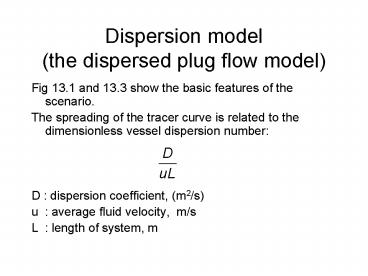
- Fig 13.1 and 13.3 show the basic features of the
scenario. - The spreading of the tracer curve is related to
the dimensionless vessel dispersion number - D dispersion coefficient, (m2/s)
- u average fluid velocity, m/s
- L length of system, m
2
- We characterize the Cpulse curve by the mean
residence time and the variance
3
Fig. 13.1 and 13.3
4
(No Transcript)
5
(No Transcript)
6
Dispersion model
- You will study the advection-dispersion equation
(5 and 6) in detail in the contaminant transport
course next term.
7
Dispersion model, D/uLlt0.01
- The solution in non-dimensional form gives the E?
vs ? curve (Fig. 13.4) similar to the E? vs ?
curve for the tanks in series model (Fig. 14.3) - Box 8 equations give the relevant relationships.
Note the limitation of D/uLlt0.01 for the
solution.
8
Fig. 13.4
9
Box 8
10
Determination of the vessel dispersion number
- Compare experimental E? vs ? curve with the
solution in Fig 13.4 to get the D/uL parameter by
one of the following methods - by calculating its variance
- by measuring its maximum height
- by measuring its width at the point of inflection
- by finding the width which includes 68 of the
area
11
- Additivity for vessels in series.
12
(No Transcript)
13
One-shot tracer input (arbitrary shape)
- The additivity of variances enables us to use
tracer inputs of arbitrary shape and use the
difference in variance to quantify the
dispersion Fig. 13.6 - For small extents of dispersion (D/uL lt 0.01) we
can also use - However, if the tracer curve shapes are very
different from symmetrical and D/uLgt0.01 the
models basic assumptions begin to fail. Using
an alternate model (tanks in series?) may be a
better idea.
14
Figure 13.6
15
Dispersion model, D/uLgt0.01
- For large D/uL values we have two sets of
solutions, for open and closed boundary
conditions. (Fig. 13.7) - Fig. 13.8 and Box 13 for closed vessel boundary
conditions. - Fig. 13.10 and Box 14-15 for open vessel boundary
conditions.
16
Figure 13.7
17
Fig. 13.8
18
Box 13
19
Fig. 13.10
20
Box 14-15
21
Example 13.1
- Based on previous example 11.1 data
22
(No Transcript)
23
(No Transcript)
24
Correlations for Dispersion number
25
- The Schmidt number captures the fluid properties
26
(No Transcript)
27
(No Transcript)
28
(No Transcript)
29
Correlations for Dispersion number
- These would help predict the dispersion number,
as opposed to running an experiment on a full
scale system.
30
Effect of dispersion on conversion
- Recall Examples 11.1 and 11.4
- Example 11.1 Residence time distribution in PFR
- Example 11.4 Impact of the RTD on conversion
- We will now quantify the effect of dispersion on
conversion using the dispersed plug flow model
31
RTD of Example 11.1
32
Example 11.4 First order reaction in non-ideal PFR
- Cpulse vs time data from Example 11.1
- -rA(0.307 min-1)CA
- Ideal PFR gives CA/CA0 0.01, i.e. XA0.99
- The reactor with E from Example 11.1 gives
- CA/CA0 0.0469, i.e. XA0.9531
33
RTD and dispersion number
- In examples 11.1 and 11.4 the nonideality of flow
was quantified by the E vs t curve - The dispersed plug flow model uses D/uL
(dispersion number) as the parameter to quantify
non-ideality. - Figures 13.19 and 13.20 relate the volume of a
reactor with given dispersion number to the
volume of an ideal PFR
34
Figures 13.9 and 13.20
- These are similar in function to Figures 6.16 and
6.17 which quantified the effect of recycle on
the performance of a PFR. - The performance of the PFR deteriorates with
increasing - Recycle ratio
- or
- D/uL
35
(No Transcript)
36
(No Transcript)
37
Example 11.4 with dispersion model
- Refer to Excel worksheet nonideal_flow.xls
38
(No Transcript)
39
(No Transcript)


