Maskless Lithography With Mirror Array - PowerPoint PPT Presentation
1 / 9
Title:
Maskless Lithography With Mirror Array
Description:
Ben Wild implemented eight Lempel-Ziv/Huffman decompress paths on a chip ... Decompress requires large memory to store block ... Each decompress path must write ... – PowerPoint PPT presentation
Number of Views:595
Avg rating:3.0/5.0
Title: Maskless Lithography With Mirror Array
1
Maskless Lithography With Mirror Array
OPTICS
LASER
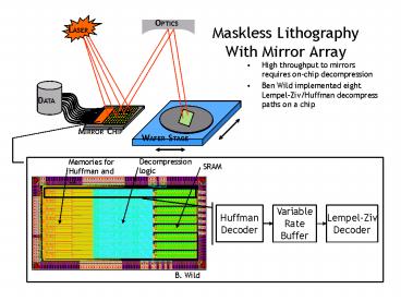
- High throughput to mirrors requires on-chip
decompression - Ben Wild implemented eight Lempel-Ziv/Huffman
decompress paths on a chip
DATA
MIRROR CHIP
WAFER STAGE
Decompression logic
Memories for Huffman and LZ
SRAM
Huffman Decoder
Lempel-Ziv Decoder
Variable Rate Buffer
2
Data Delivery Problem
- Goals
- 50nm minimum feature size
- 1nm edge placement
- 300mm wafer (one layer) per minute
- Pixel Based Solution
- 25nm pixels, 5-bit grayscale
- Prototype chip by Ben Wild complete
- 8 decompress paths (Lempel-Ziv, Huffman)
- SRAM (1024x8) memory for mirror interface
- Throughput 8 x 8bits x 100MHz 6.4Gb/s
- Prototype 2
- better compression/decompression
- Improve mirror interface throughput
3
Compression/Decompression Algorithms
- Runlength Encoding (RLE)
- Layout data has large, homogeneous blocks
- A simple runlength encode can greatly improve the
effectiveness of BW or LZ - Burrows-Wheeler (BW)
- Sort one block context, then compress with simple
locally adaptive algorithm - Decompress requires large memory to store block
- Results compression not as good as LZ,
decompress more complex than LZ - Lempel-Ziv (LZ)
- Simple decompress outperforms BW
- Best when preceded by RLE
4
Lempel-Ziv
- Basic algorithm behind ZIP
- Simplest algorithm that achieves good compression
- Compacts data by replacing strings with the
offset and length of a matching string in the
history buffer. If no match can be found,
characters are represented by literals. - lt0, literalgt
- lt1, history buffer offset, match lengthgt
- Compression ratio depends on the size of the
history buffer and maximum match length
Match flag
5
Runlength encode Lempel-Ziv
- By preceding LZ with runlength encoding (RLE4M),
the LZ compression curve is shifted to the left - Benefits for decompress hardware
- Smaller buffer size ? smaller chip
- Runlength encoding drops the LZ throughput by a
factor of about 20 - Runlength decoder is very simple
6
Prototype Layout
- Energy source flash rate 10kHz ? 188 million
mirrors to meet specs
- This high aspect ratio arrangement yields a
minimum 8,200 mirrors on each bitline
7
Digital/Analog Interface
- Total error budget is 0.5nm per 25nm pixel ?
assume 1 error for DAC, interconnect, and Sample
Hold
8
Interconnect
- Requirements
- Each decompress path must write 4,100 mirrors
- Total write time is 100us ? 12ns average write
time for half cycle - Given
- Drain capacitance 0.15fF (Josh Garretts model)
- Wire cap 100f/mm
- Interconnect resistance 2k (does not account
for DAC and SH) - Worst case write time (simple RC model to 99.5)
20ns - Correct order of magnitude!!
- We are now working on extracting the R and C from
the layout for a more accurate analysis
9
DAC and Sample Hold
- Two approaches for DAC
- Very precise 5-bit DAC (requires larger
transistors) - Less precise 6-bit DAC with feedback (CCD camera)
to correct for errors (requires less area) - Sample Hold
- Noise is not a problem because of the size of the
mirror cap - Charge leakage
- Body biasing and negative gate voltage can
minimize this problem - Charge injection
- Clock feedthrough
- With a clever design, the DAC can pre-correct
for most interconnect and sample hold errors


