Parameters - PowerPoint PPT Presentation
Title:
Parameters
Description:
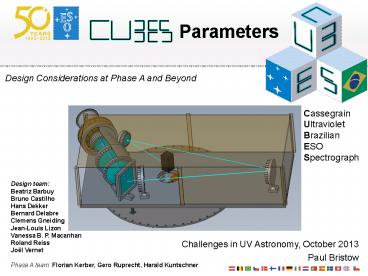
Parameters Design Considerations at Phase A and Beyond Cassegrain Ultraviolet Brazilian ESO Spectrograph Design team: Beatriz Barbuy Bruno Castilho Hans Dekker – PowerPoint PPT presentation
Number of Views:51
Avg rating:3.0/5.0
Title: Parameters
1
- Parameters
Design Considerations at Phase A and Beyond
Cassegrain Ultraviolet Brazilian ESO Spectrograph
Design team Beatriz Barbuy Bruno Castilho Hans
Dekker Bernard Delabre Clemens Gneiding Jean-Louis
Lizon Vanessa B. P. Macanhan Roland Reiss Joël
Vernet Phase A team Florian Kerber, Gero
Ruprecht, Harald Kuntschner
Challenges in UV Astronomy, October 2013 Paul
Bristow
2
Overview
- Requirements that drive the design
- Achieving high efficiency
- Opto-mechanical design
- Slicer
- Detector Array
- Optical Bench
- Atmospheric Dispersion Compensation
- Calibration
- Summary
3
Not so many parameters
- In geometry theres no 3D object much simpler
than a CUBE (fully described by one parameter) - Except maybe a SPHERE (ESOs already got one,
nearly) - or a TETRAHEDRON.
- Simple means
- Quicker
- Less risk
- Cheaper
- Easier to operate
- Easier to calibrate
4
TTTLRS
- Top Three Top Level Requirements
- Significantly improve upon throughput (or better
S/N) of existing ground based UV spectrographs
USP! - Achieve R20,000
- Cover the wavelength range 310-360nm (302-385nm)
- Actually four
- VLT gt
- 8m Diameter collecting area
- Paranal seeing and extinction
- Interface with VLT infrastructure
- Campaign mode
5
Achieving high efficiency
- Atmosphere
- Optical design
- Cass focus
- Slicer (no AO)
- Single dispersive element
- Minimum surfaces
- Grating
- Detector
Cassegrain 77 Nasmyth 65
6
Comparison to FORS2,UVES X-shooter
7
Choices arising from TTTLRs
Design Aspect Implications
Cassegrain Flexure away from Zenith
Slicer (no AO) Complexity of AG DRS Noise
No X-dispersion or pre-dispersion Resolution/wavelength range
Minimal surfaces Difficulty/cost of optics
High efficiency grating New technology/cost
High QE detector New technology/cost
Ground based/Paranal Atmosphere
8
Evolving Opto-mechanical Design Detector Array
- Long detector array
- 3 or 4 4K 2K 15µm 15µm
- 250mm x 30mm (200pix gaps)
- Large (but feasible) detector vessel
- One mode (plus interlace)
- No pre-disperser, grating operating in 1st order
gtno tuneable wavelength range (without losing
efficiency) - Several methods of recovering the wavelengths
that fall into the detector gaps are under
consideration
9
Evolving Opto-mechanical Design Slicer
- Phase A slicer design had three very efficient
slitlets - Smaller slitlets
- Larger wavelength range for given detector array
size and resolving power - More slitlets needed gt signal spread over more
pixels - Detailed Simulations to investigate optimal
number of slitlets and their widths - Binning, RON, Dark current
- Integration times, Targets
- Seeing, Sky brightness
10
Evolving Opto-mechanical Design Slicer
11
Evolving Opto-mechanical Design Slicer
- MUSE style slicer, gt7 slices lt0.3 slitlet
widths
12
Evolving Opto-mechanical Design Optical Bench
13
Evolving Opto-mechanical Design Camera and DV
14
Evolving Opto-mechanical Design Pre-slicer
15
Evolving Opto-mechanical Design ADC?
- Observe along parallactic (default)
- Flexure easier to handle
- Airmass restrictions anyway
16
Evolving Opto-mechanical Design Calibration Unit
- Talk by Florian Kerber on LDLS for flats
- Potential wavecal sources, Hollow Cathode Lamps
- Th-Ar or Th-Ne
- Pt/Cr-Ne
- Tellurics for absolute wavelength ZP?
- Simultaneous wavelength calibration?
- Repeatability/stability
- Automatic flexure compensation
- Stray light
- To be decided
17
Summary
- The CUBES design is dedicated to providing
significant SNR improvement relative to existing
ground based UV spectrographs - CUBES will be easy to build, easy to operate and
maintain and easy to calibrate
Slicer No. slicesgt7 slitlet widthslt0.3
Transmission grating 3200mm-1 1st order Ruled width260mm gt80_at_320nm
Detector Array 4 4K 2K 15µm15µm250mm x 30mmQEgt85 _at_320nm Dark current lt0.001e-/pix/sRON lt2.5e-
Wavelength Range 302-390nm (TBC)
Resolving Power 20,000
18
End of Talk


