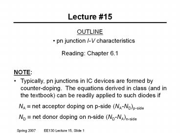
OUTLINE
1 / 22
Title: OUTLINE
1
Lecture 15
- OUTLINE
- pn junction I-V characteristics
- Reading Chapter 6.1
- NOTE
- Typically, pn junctions in IC devices are formed
by counter-doping. The equations derived in
class (and in the textbook) can be readily
applied to such diodes if - NA ? net acceptor doping on p-side
(NA-ND)p-side - ND ? net donor doping on n-side (ND-NA)n-side
2
Linearly Graded Junction
3
Biased PN Junctions
Note that VA should be significantly smaller than
Vbi (Otherwise, we cannot assume low-level
injection)
4
Effect of Bias on Electrostatics
5
pn Junction Electrostatics, VA ? 0
- Built-in potential Vbi (non-degenerate doping)
- Depletion width W
6
- Electric field distribution e(x)
- Potential distribution V(x)
7
Peak Electric Field
- For a one-sided junction
- therefore
8
Current Flow - Qualitative
9
Current Flow in a pn Junction Diode
- When a forward bias (VAgt0) is applied, the
potential barrier to diffusion across the
junction is reduced - Minority carriers are injected into the
quasi-neutral regions gt Dnp gt 0, Dpn gt 0 - Minority carriers diffuse in the quasi-neutral
regions, recombining with majority carriers
10
- Current density J Jn(x) Jp(x)
- J is constant throughout the diode, but Jn(x) and
Jp(x) vary with position
11
Ideal Diode Analysis Assumptions
- Non-degenerately doped step junction
- Steady-state conditions
- Low-level injection conditions prevail in the
quasi-neutral regions - Recombination-generation is negligible in the
depletion region - i.e. Jn Jp are constant inside the depletion
region
12
Ideal Diode Analysis Approach
- Solve the minority-carrier diffusion equations in
quasi-neutral regions to obtain
Dnp(x,VA),Dpn(x,VA) - apply boundary conditions
- p-side Dnp(-xp), Dnp(-?)
- n-side Dpn(xn), Dpn(?)
- Determine minority-carrier current densities in
quasi-neutral regions - Evaluate Jn at x-xp and Jp at xxn
- J(VA) Jn(VA)x-xp Jp(VA )xxn
13
Carrier Concentrations at xp, xn
Consider the equilibrium (VA 0) carrier
concentrations
n-side
p-side
If low-level injection conditions prevail in the
quasi-neutral regions when VA ? 0, then
14
Law of the Junction
The voltage VA applied to a pn junction falls
mostly across the depletion region (assuming that
low-level injection conditions prevail in the
quasi-neutral regions). We can draw 2 quasi-Fermi
levels in the depletion region
15
Excess Carrier Concentrations at xp, xn
n-side
p-side
16
Example Carrier Injection
A pn junction has NA1018 cm-3 and ND1016 cm-3.
The applied voltage is 0.6 V. Question What
are the minority carrier concentrations at the
depletion-region edges? Answer Question
What are the excess minority carrier
concentrations? Answer
17
Excess Carrier Distribution
- From the minority carrier diffusion equation
- We have the following boundary conditions
- For simplicity, we will develop a new coordinate
system - Then, the solution is of the form
18
- From the x ? boundary condition, A1 0.
- From the x xn boundary condition,
- Therefore,
- Similarly, we can derive
19
pn Diode I-V Characteristic
p-side
n-side
20
(No Transcript)
21
Diode Saturation Current I0
- I0 can vary by orders of magnitude, depending on
the semiconductor material - In an asymmetrically doped pn junction, the term
associated with the more heavily doped side is
negligible - If the p side is much more heavily doped,
- If the n side is much more heavily doped,
22
Summary
- The total voltage dropped across a pn junction is
Vbi-VA - Depletion-layer width
- Peak electric field
- Under forward bias (VA gt 0), the potential
barrier to carrier diffusion is reduced - minority carriers are injected and diffuse in
the quasi-neutral regions - Diode current


![[PDF] DOWNLOAD FREE Clinical Outline of Oral Pathology: Diagnosis and](https://s3.amazonaws.com/images.powershow.com/10076578.th0.jpg?_=20240711025)


![[READ]⚡PDF✔ Black Letter Outline on Contracts (Black Letter Outlines) 5th Edition](https://s3.amazonaws.com/images.powershow.com/10044064.th0.jpg?_=20240531080)


